1-6
DECcolorwriter 1000
1
General Information
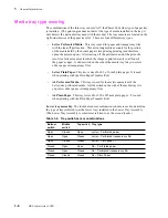
Media tray type sensing
The combinations of the three tray sensors “tell” the Phaser 200e what type of paper tray
is installed. (The print engine does not detect the type of media installed in the tray; it
only detects the particular tray used with the media.) The tray sensors are located on the
right-side interior of the paper tray slot. There are four different tray types:
n
Letter Perforated Media. This tray is used for paper and transparency film
with the tear-off perforation. This extra-long media accounts for the portion
of the media held by the drum's paper clamp during printing (and therefore
cannot be printed upon.) After tearing off the perforated end of the print, the
result is a letter-size print in which the image is printed evenly to all four of
the paper’s edges. A slide switch on the side of the media tray lets you select
either paper or transparency film.
n
Letter Plain Paper. This tray is sized for 8.5 x 11-inch plain paper. It is used
when printing with the Plain Paper Transfer Roll.
n
A4 Perforated Media. This tray is used for the metric equivalent of the
Letter-size perforated media. A slide switch on the side of the media tray lets
you select either paper or transparency film.
n
A4 Plain Paper. This tray is sized for 210 x 297-mm plain paper. It is used
when printing with the Plain Paper Transfer Roll.
Lower tray assembly. The identical sensor combination scheme is used to determine
the type of tray (referred to as the lower tray) installed in the Lower Tray Assembly.
(The Lower Tray Assembly is sometimes referred to as the second feeder.)
Table 1-2. Tray switch sensor combinations
Bottom
switch
Middle
switch
Top switch
Tray type
Open
Closed
Open
Letter – Perforated paper
Open
Open
Closed
Letter – Perforated transparency film
Open
Closed
Closed
Letter – Plain paper
Closed
Open
Open
A4 – Perforated paper
Closed
Open
Closed
A4 – Perforated transparency film
Closed
Closed
Closed
A4 – Plain Paper
Summary of Contents for DECcolorwriter 1000
Page 11: ...Service Manual xi...
Page 16: ...Service Manual xv...
Page 56: ...2 24 DECcolorwriter 1000 2 Installing the Printer and Drivers...
Page 64: ...3 8 DECcolorwriter 1000 3 Verifying the Printer and Host Connections...
Page 70: ...4 6 DECcolorwriter 1000 4 Key Operator Training...
Page 170: ...8 46 DECcolorwriter 1000 8 FRU Disassembly Assembly...
Page 190: ...9 20 DECcolorwriter 1000 9 Checks and Adjustments...
Page 195: ...Service Manual A 5 Field Replaceable Units List A...
Page 198: ...A 8 DECcolorwriter 1000 A Field Replaceable Units List...
Page 204: ...C 6 DECcolorwriter 1000 C Wiring Diagrams...
Page 208: ...D 4 DECcolorwriter 1000 D Test Pattern Generator...

