1-8
DECcolorwriter 1000
1
General Information
Rear panel
Connectors
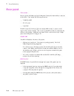
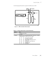
The rear panel of the DECcolorwriter 1000 printer features the host interface connectors
to the printer. They include the following connectors:
n
Standard parallel
n
RS-232 serial
n
LocalTalk
The DECcolorwriter 1000 rear panel also features DIP switches to control certain
aspects of the printers’ imaging. You can also use the DIP switches for controlling the
self-tests of the printers’ image processor board. Refer to the Section 6 topic “Image
processor self-diagnostics” on page 6-30.
Health LED
A health LED indicates the status of the printer.
n
Blinking (at a steady rate): The printer is operating normally. The LED
blinks irregularly during diagnostics.
If a soft error occurs, the image processor board will operate, but in a reduced
capacity. Soft failures include failure of expansion memory SIMMs or any of
the interface ports. When a soft error occurs, the printer automatically prints
a start-up page listing the error.
n
On or Off: A hard error condition has occurred that would keep the image
processor board from operating.
TEST button
The TEST button, located at the bottom right rear corner of the printer, has two
functions:
n
Following normal power-up, pressing the TEST button for 5 seconds prints a
composite test pattern. Refer to Figure B-1 in Appendix B, Test Patterns for
a sample of the composite test pattern.
n
Pressing and holding the TEST button while you turn on the printer places
the printer in Service mode.
Summary of Contents for DECcolorwriter 1000
Page 11: ...Service Manual xi...
Page 16: ...Service Manual xv...
Page 56: ...2 24 DECcolorwriter 1000 2 Installing the Printer and Drivers...
Page 64: ...3 8 DECcolorwriter 1000 3 Verifying the Printer and Host Connections...
Page 70: ...4 6 DECcolorwriter 1000 4 Key Operator Training...
Page 170: ...8 46 DECcolorwriter 1000 8 FRU Disassembly Assembly...
Page 190: ...9 20 DECcolorwriter 1000 9 Checks and Adjustments...
Page 195: ...Service Manual A 5 Field Replaceable Units List A...
Page 198: ...A 8 DECcolorwriter 1000 A Field Replaceable Units List...
Page 204: ...C 6 DECcolorwriter 1000 C Wiring Diagrams...
Page 208: ...D 4 DECcolorwriter 1000 D Test Pattern Generator...

