Service Manual
5-7
Theory of Operation
5
CPU
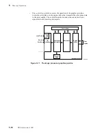
All DECcolorwriter 1000 print engine CPUs consist of a microprocessor, ROM, RAM
and a clock circuit. The CPU is the heart of the print engine. It controls the timing
controller, the mechanical controller, and print engine diagnostics.
Interface buffers
The interface buffers receive data from the image processor board, where the image data
was received from the host computer and processed into data for the print engine. The
interface buffer routes received data signals to the data controller.
Data controller and line buffers
The data controller receives input data from the interface and stores it in a data buffer.
The data buffer contains two buffers: one buffer holds the current line of image data
being transmitted to the print engine and the other buffer holds the preceding seven lines
of image data received by the print engine. When the data buffers contain all eight lines
of data, then the data controller transfers the data to the heat controller.
Heat controller (dot compensation)
Each thermal heating element must receive sufficient energy to melt wax properly. Too
much energy and the wax dot smears when printed. Too little energy, and the wax dot is
ill-formed and does not adhere to the paper. In the heat controller, the data of the current
raster line to be printed is compared with the seven previously printed lines. The dot
compensator determines when, and for how long, the individual thermal head elements
should be energized to properly melt wax onto the paper. This comparison accounts for
the thermal energy stored in each heating element from its previous dot printing action as
well as the thermal energy picked up from adjacent heating elements.
In this comparison, the heat controller determines, for each dot to be printed, if the
heating element was used to print any dots during the last seven lines, and also if any
neighboring dots were or will be printed next to the dot in question. Knowing this
history, the heat controller can determine how long to sustain the voltage pulse to the
dot's heating element to correctly print the dot. This information is transferred to the line
memory buffer.
Summary of Contents for DECcolorwriter 1000
Page 11: ...Service Manual xi...
Page 16: ...Service Manual xv...
Page 56: ...2 24 DECcolorwriter 1000 2 Installing the Printer and Drivers...
Page 64: ...3 8 DECcolorwriter 1000 3 Verifying the Printer and Host Connections...
Page 70: ...4 6 DECcolorwriter 1000 4 Key Operator Training...
Page 170: ...8 46 DECcolorwriter 1000 8 FRU Disassembly Assembly...
Page 190: ...9 20 DECcolorwriter 1000 9 Checks and Adjustments...
Page 195: ...Service Manual A 5 Field Replaceable Units List A...
Page 198: ...A 8 DECcolorwriter 1000 A Field Replaceable Units List...
Page 204: ...C 6 DECcolorwriter 1000 C Wiring Diagrams...
Page 208: ...D 4 DECcolorwriter 1000 D Test Pattern Generator...


