5-8
DECcolorwriter 1000
5
Theory of Operation
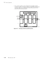
Thermal head controller
The thermal head controller uses the information received from the heat controller, in
conjunction with timing signals, to drive the thermal head with the data stored in the line
memory buffer. The head controller generates four different strobes. These four strobes
are combined to provide seven drive pulses ranging from 435 uS for “cold” thermal
elements, to 200 uS for “hot” elements. The drive pulses are combinations of these pulse
widths: 145 uS, 120 uS, 90 uS and 80 uS pulses. During printing, the strobe length is
varied, based on the overall thermal head temperature and the volume of dots printed in a
line. The voltage level of the pulse is fixed at 25.5 VDC.
Thermal head
The thermal head is the device that melts wax dots onto paper. It contains a row of 2496
solid-state heating elements. (Only a maximum of 2440 are actually used.) The actual
number of elements used during a particular print depends on the paper size (A or A4)
and the image to be printed. The thermal head prints raster lines parallel to the short axis
of the paper.
Earlier, in the topic “The print process,” we said that the print engine prints one line at a
time; this is not exactly the case, it just appears that way. To simplify its electrical
design, the print engine actually uses a drive signal multiplexing scheme to energize the
heating elements. During printing, the head controller activates a pair of heating element
segments from eight heating segments of the thermal head. (Individual elements in the
segments may or may not be energized depending upon whether the element is to print a
dot; it is just that segments are printed as pairs.) Following the printing of the first pairs
of segments, the head controller energizes the second pair of segments from the eight
heating element segments, then the third pair. Energizing the fourth pair of segments
completes the raster line printing. A line is printed in 1.8 msec.
Mechanical controller
The printer engine mechanical controller interfaces the CPU to the print engine’s motors,
sensors, solenoids and fans. By interpreting signals from the sensors, buffered by the
mechanical controller, the CPU keeps track of the paper drum position, transfer roll
position and paper position during printing. Based on this information the CPU
determines the proper time to transmit signals to the mechanical controller to advance
the paper, energize a solenoid, or check a sensor.
Internal test pattern generator
This circuit produces the print engine's internal test patterns. The test pattern algorithms
are stored in ROM. The internal test pattern data are routed to the interface block and
pass through the rest of the print engine just as regular image data would.
Summary of Contents for DECcolorwriter 1000
Page 11: ...Service Manual xi...
Page 16: ...Service Manual xv...
Page 56: ...2 24 DECcolorwriter 1000 2 Installing the Printer and Drivers...
Page 64: ...3 8 DECcolorwriter 1000 3 Verifying the Printer and Host Connections...
Page 70: ...4 6 DECcolorwriter 1000 4 Key Operator Training...
Page 170: ...8 46 DECcolorwriter 1000 8 FRU Disassembly Assembly...
Page 190: ...9 20 DECcolorwriter 1000 9 Checks and Adjustments...
Page 195: ...Service Manual A 5 Field Replaceable Units List A...
Page 198: ...A 8 DECcolorwriter 1000 A Field Replaceable Units List...
Page 204: ...C 6 DECcolorwriter 1000 C Wiring Diagrams...
Page 208: ...D 4 DECcolorwriter 1000 D Test Pattern Generator...


