Service Manual
5-11
Theory of Operation
5
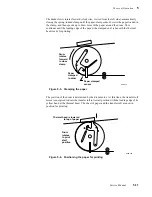
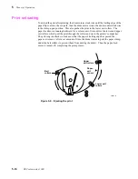
The drum slowly rotates forward (clockwise, viewed from the left side), automatically
closing the spring-loaded clamp until the paper-clamp sensor detects the paper loaded in
the clamp, and then speeds up to draw more of the paper around the drum. This
continues until the leading edge of the paper (the clamped end) is beneath the thermal
head, ready for printing.
The position of the drum is determined by the drum motor. At this time, the transfer roll
motor is energized to draw the transfer roll to its start position with the leading edge of its
yellow band at the thermal head. The sheet of paper and the transfer roll are now in
position for printing.
Figure 5-5. Clamping the paper
Figure 5-6. Positioning the paper for printing
8699-12
Drum
rotates
forward
to close
clamp
Paper
clamped
to drum
Paper clamped
sensor
8699-13A
Drum
rotates
to print
start
position
Thermal head is lowered
to top of paper
Summary of Contents for DECcolorwriter 1000
Page 11: ...Service Manual xi...
Page 16: ...Service Manual xv...
Page 56: ...2 24 DECcolorwriter 1000 2 Installing the Printer and Drivers...
Page 64: ...3 8 DECcolorwriter 1000 3 Verifying the Printer and Host Connections...
Page 70: ...4 6 DECcolorwriter 1000 4 Key Operator Training...
Page 170: ...8 46 DECcolorwriter 1000 8 FRU Disassembly Assembly...
Page 190: ...9 20 DECcolorwriter 1000 9 Checks and Adjustments...
Page 195: ...Service Manual A 5 Field Replaceable Units List A...
Page 198: ...A 8 DECcolorwriter 1000 A Field Replaceable Units List...
Page 204: ...C 6 DECcolorwriter 1000 C Wiring Diagrams...
Page 208: ...D 4 DECcolorwriter 1000 D Test Pattern Generator...

