5-12
DECcolorwriter 1000
5
Theory of Operation
Printing
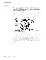
After checking the transfer roll's position (through the transfer roll mark sensors) the
thermal head lift motor rotates an eccentric cam to push the thermal head down from its
standby position to its print position, sandwiching the transfer roll and paper together
between the thermal head and the drum.
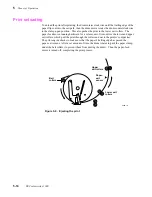
Printing begins as the drum slowly rotates forward (clockwise) drawing the paper and
the transfer roll past the thermal head where wax is melted from the transfer roll onto the
paper to form a printed image. Contact friction between the moving paper and the
transfer roll moves the transfer roll past the thermal head at the same rate as the paper.
The sheet of paper is drawn past the thermal head three times to form a complete image.
When the first pass (yellow printing) is completed, the thermal head lift motor raises the
thermal head to its standby position allowing the paper clamp to pass underneath. When
the paper reaches the print-start position, the thermal head lift motor rotates to bring the
thermal head back to the print position, and printing continues with magenta printing.
This process repeats once more for cyan printing and then the print is ready to be
unloaded to the printer's output tray. (During forward rotation, the drum stops are simply
pushed out of the way. The drum stops can only open the clamp during reverse drum
rotation.)
Figure 5-7. Printing on the paper
8699-14A
Thermal head
Transfer
roll
Paper
Drum and
transfer roll
move at
same rate
Drum stops at
each end of the drum
pivot out of the way
Transfer roll
mark sensors
Summary of Contents for DECcolorwriter 1000
Page 11: ...Service Manual xi...
Page 16: ...Service Manual xv...
Page 56: ...2 24 DECcolorwriter 1000 2 Installing the Printer and Drivers...
Page 64: ...3 8 DECcolorwriter 1000 3 Verifying the Printer and Host Connections...
Page 70: ...4 6 DECcolorwriter 1000 4 Key Operator Training...
Page 170: ...8 46 DECcolorwriter 1000 8 FRU Disassembly Assembly...
Page 190: ...9 20 DECcolorwriter 1000 9 Checks and Adjustments...
Page 195: ...Service Manual A 5 Field Replaceable Units List A...
Page 198: ...A 8 DECcolorwriter 1000 A Field Replaceable Units List...
Page 204: ...C 6 DECcolorwriter 1000 C Wiring Diagrams...
Page 208: ...D 4 DECcolorwriter 1000 D Test Pattern Generator...

