Service Manual
ix
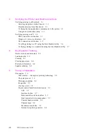
8
FRU Disassembly/Assembly
Required tools
8-1
Lower tray assembly
8-2
Printer cabinet panels
8-3
Paper-feed module
8-5
Accessing the pick roller, aligning roller, and the lower feed roller
8-6
Paper-pick roller, clutch, and paper-empty flag
8-9
Lower aligning roller, clutch, and paper-pass sensorþ1þflag
8-11
Removing the upper aligning roller
8-13
Removing the feedþroller
8-14
Removing the exitþrollers
8-15
Bail roller assembly
8-16
Thermal head
8-17
Drum
8-19
Motors
8-23
Paper-feed motor
8-23
Drum motor
8-24
Transfer roll take-upþmotor
8-25
Thermal head lift motor
8-27
Sensors and switches
8-29
Paper-pass sensorþ1 and paper-empty sensor
8-29
Thermal head position sensors
8-29
Transfer roll mark sensors
8-29
Paper-pass sensorþ2 and trayþsensor
8-30
Transfer roll lowþsensor
8-33
Paper clamp sensor
8-34
Card cage and power supply
8-35
Circuit boards
8-37
Power supply circuit board
8-37
Paper-feed circuitþboard
8-39
Engine control board
8-39
Card cage interconnect board
8-41
I/O board
8-42
Image processor board
8-43
RAM SIMM
8-44
Font module
8-45
Summary of Contents for DECcolorwriter 1000
Page 11: ...Service Manual xi...
Page 16: ...Service Manual xv...
Page 56: ...2 24 DECcolorwriter 1000 2 Installing the Printer and Drivers...
Page 64: ...3 8 DECcolorwriter 1000 3 Verifying the Printer and Host Connections...
Page 70: ...4 6 DECcolorwriter 1000 4 Key Operator Training...
Page 170: ...8 46 DECcolorwriter 1000 8 FRU Disassembly Assembly...
Page 190: ...9 20 DECcolorwriter 1000 9 Checks and Adjustments...
Page 195: ...Service Manual A 5 Field Replaceable Units List A...
Page 198: ...A 8 DECcolorwriter 1000 A Field Replaceable Units List...
Page 204: ...C 6 DECcolorwriter 1000 C Wiring Diagrams...
Page 208: ...D 4 DECcolorwriter 1000 D Test Pattern Generator...

