Service Manual
6-3
Troubleshooting
6
2.
Once the READY light is on (not blinking), press and hold the TEST button
for 5 seconds. The printer should print out a test pattern.
If the printer prints a test pattern, then the print engine is working correctly and the
printer's problem resides with its image processor board. Refer to the later topic “Image
processor self-diagnostics” on page 6-30.
If the printer does not print a test pattern, then a problem exists with the print engine.
Proceed with the topic “Verifying power supply operation” below.
Verifying power supply operation
Verifying the power supply involves four steps:
n
Measuring the input and output voltages
n
Inspecting the power supply fuses
n
Checking its +24 VDC safety interlocks
n
Testing for a shorted motor which would shut down the power supply
Measuring power supply voltages
1.
Turn off the printer and unplug it from its power outlet.
2.
AC Input: With the VOM set to measure AC voltages, measure for power
being supplied to the printer. It should measure between 87 to 128 VAC (115
VAC nominal) or 174 to 250 VAC (220 VAC nominal). Ensure that the
switch is correctly set.
3.
Remove the left side cabinet panel to access the wiring harnesses plugged into
the print engine control board.
4.
Plug in the printer and turn it on.
5.
DC Output: With the VOM set to measure DC voltages, measure for +5
VDC and +24 VDC (this actually measures 25.5 VDC). The following
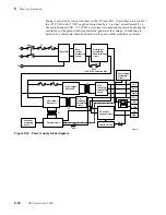
illustration shows the test points. Be aware that the +24 VDC supplied to the
motors is supplied directly through the cover-open safety interlock switches.
6.
Thermal head voltage: With the VOM set to measure DC voltages, measure
for about 25.5 VDC at Pin 1 through 6 of the thermal head's 12-pin power
connector. Pins 7 through 12 are ground.
7.
Engine fan: Ensure that the power supply fan runs while the printer is turned
on. The fan blows into the card cage (toward the image processor board).
Required tools
n
#1 POSIDRIV® screwdriver
n
Volt-ohm-meter (VOM)
Summary of Contents for DECcolorwriter 1000
Page 11: ...Service Manual xi...
Page 16: ...Service Manual xv...
Page 56: ...2 24 DECcolorwriter 1000 2 Installing the Printer and Drivers...
Page 64: ...3 8 DECcolorwriter 1000 3 Verifying the Printer and Host Connections...
Page 70: ...4 6 DECcolorwriter 1000 4 Key Operator Training...
Page 170: ...8 46 DECcolorwriter 1000 8 FRU Disassembly Assembly...
Page 190: ...9 20 DECcolorwriter 1000 9 Checks and Adjustments...
Page 195: ...Service Manual A 5 Field Replaceable Units List A...
Page 198: ...A 8 DECcolorwriter 1000 A Field Replaceable Units List...
Page 204: ...C 6 DECcolorwriter 1000 C Wiring Diagrams...
Page 208: ...D 4 DECcolorwriter 1000 D Test Pattern Generator...


