4-5
User Maintenance
Cleaning and Servicing the Color Print Head
Also the color ink-jet print head demands special care as far as nozzle cleaning
is concerned.
Given their particular structure, dust or the drying-out of exposed ink can
easily clog the nozzles.
Listed below are some useful tips that will guarantee the optimum use of the
print head.
- Remove the print head from its sealed container only when you are about to
install it in the printer.
The print head has an 18-month warranty if stored in its own sealed con-
tainer, otherwise the warranty is reduced to about six months (both warranty
periods are cumulative).
- Never rest the print head on its nozzle or electric contact sides. Never rest
the print head on heat sources, air conditioners, nor on dirty or dusty sur-
faces.
- After installing the new color print head the printer will automatically run a
nozzle bleed cycle, therefore the Prime function is not available for color
print heads.
- After a print job, tightly seal the nozzle bay so the nozzles are protected
against dust and to avoid the ink from drying-out when exposed for a certain
period of time. Since on the LJ 110/120 this operation is carried out auto-
matically after a few seconds of printer inactivity, wait a few seconds before
powering off the machine after a print job.
If a black out occurs while the printer is on, power off the printer and
manually push the print head to its farthest right-hand position.
- Whenever removing the color print head from the printer, make sure to store
it in the print head storage box supplied with the LJ 120 or the LJ 110 color
kit. This will ensure that the ink on the print head does not dry-out.
S-4.PM5
11/7/94, 17:02
5
Summary of Contents for DECcolorwriter 120ic
Page 58: ...3 21 Installation Fig 3 21 Fonts selector switches settings S 3 PM5 11 7 94 17 16 21 ...
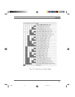
Page 59: ...3 22 Installation Fig 3 22 Character sets selector switches settings S 3 PM5 11 7 94 17 16 22 ...
Page 60: ...3 23 Installation Fig 3 23 Character sets selector switches settings S 3 PM5 11 7 94 17 16 23 ...
Page 78: ...7 3 Electrical Interconnections Fig 7 1 Main board S 7 PM5 3 14 97 3 38 PM 3 ...

