8-5
Parts Replacement
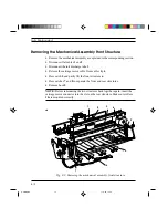
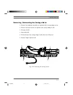
Removing / Remounting the Mechanical Assembly
•
Disassemble the base from the frame as explained in previous section.
•
Disconnect the print head's flat cables from connectors 1 and 2.
•
Press catch 3 to release the mechanical assembly from the electronic board
and power supply support and remove connectors 4 and 5.
1
2
3
4
5
Fig. 8-4: Removing the mechanical assembly
S-8.PM5
11/7/94, 17:31
5
Summary of Contents for DECcolorwriter 120ic
Page 58: ...3 21 Installation Fig 3 21 Fonts selector switches settings S 3 PM5 11 7 94 17 16 21 ...
Page 59: ...3 22 Installation Fig 3 22 Character sets selector switches settings S 3 PM5 11 7 94 17 16 22 ...
Page 60: ...3 23 Installation Fig 3 23 Character sets selector switches settings S 3 PM5 11 7 94 17 16 23 ...
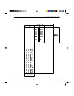
Page 78: ...7 3 Electrical Interconnections Fig 7 1 Main board S 7 PM5 3 14 97 3 38 PM 3 ...


