Functional Description 2-9
Resistors actuation circuit specifications:
The resistors are divided into four groups; two of which contain 12 resistors and
two 13. Each group can be controlled by only one resistor at a time and therefore
no more than 4 resistors can be controlled simultaneously.
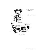
In addition, to avoid induction phenomenon’s between adjacent resistors/nozzles,
the drive will be carried out in a particular sequence (Fig. 2-6).
Fig 2-6 Resistor drive sequence
Each resistor group is controlled by a 18.8 V driver circuit. For correct head
functions, the above voltage must be stabilized.
Characteristic disadvantages which could occur with lower voltages are: lack of
bubble ejection if the head is not used for a short period, lack of bubble ejection
with low temperature. Higher voltage may provoke excess bubble commands or
the absence of command due a resistor deterioration.
Summary of Contents for DECcolorwriter 520ic
Page 1: ...DECwriter 500i DECcolorwriter 520ic LJ500 and LJ520 Service Manual EK LJ50E SV A01...
Page 18: ......
Page 70: ......
Page 74: ......
Page 78: ......
Page 80: ...Electrical Interconnections 8 2 8 2 POWER SUPPLY BOARD...
Page 81: ...Electrical Interconnections 8 3 8 3 POWER SUPPLY CIRCUIT ON MAIN BOARD...
Page 84: ......


