Functional Description 2-13
Resistor enabling circuit specifications:
The resistors are divided into four groups; one contain 12 resistors and the other
three 13. Each group can be controlled by only one resistor at a time and therefore
no more than 4 resistors can be controlled simultaneously.
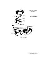
To avoid induction phenomenon’s between adjacent resistors, the drives are
carried out in the sequence illustrated in figure 2-9.
Fig. 2-9 Resistor drive sequence
Each resistor group is controlled by an 18.8 V driver circuit. For correct head
functioning, the above voltage must be stabilized.
Characteristic disadvantages which could occur with lower voltages are: lack of
bubble ejection if the head is not used for a short period, lack of bubble ejection
with low temperature.
Higher voltage may provoke excess bubble commands or the absence of
command due to resistor deterioration.
Summary of Contents for DECcolorwriter 520ic
Page 1: ...DECwriter 500i DECcolorwriter 520ic LJ500 and LJ520 Service Manual EK LJ50E SV A01...
Page 18: ......
Page 70: ......
Page 74: ......
Page 78: ......
Page 80: ...Electrical Interconnections 8 2 8 2 POWER SUPPLY BOARD...
Page 81: ...Electrical Interconnections 8 3 8 3 POWER SUPPLY CIRCUIT ON MAIN BOARD...
Page 84: ......

