Installation 3-14
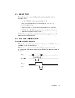
A 36 pin connection cable is supplied with the system, and this must not exceed
2.5 metres.
The figure below shows the 36 pin Amphenol connector for the parallel interface
connection, indicating the transmission signals.
19 GROUND
20 GROUND
21 GROUND
22 GROUND
23 GROUND
24 GROUND
25 GROUND
26 GROUND
27 GROUND
28 GROUND
29 GROUND
30 GROUND
31 INIT.
32 ERROR
33 LOGIC GROUND
34 NC
35 +5 V (PULL-UP; 3.3K ohm)
36 INPUT / SELECT IN
D 17
E 10
T 14
Y 12
D 16
E 01
1 03
2 04
3 05
4 06
5 07
6 08
7 09
Y 11
C 15
V 18
E 13
0 02
STROBE
DATA 0
DATA 1
DATA 2
DATA 3
DATA 4
DATA 5
DATA 6
DATA 7
ACK
BUSY
PAPER EMPTY
ON LINE
AUTOFEED XT
NC
LOGIC GROUND
FRAME GROUND
+5 V
Summary of Contents for DECcolorwriter 520ic
Page 1: ...DECwriter 500i DECcolorwriter 520ic LJ500 and LJ520 Service Manual EK LJ50E SV A01...
Page 18: ......
Page 70: ......
Page 74: ......
Page 78: ......
Page 80: ...Electrical Interconnections 8 2 8 2 POWER SUPPLY BOARD...
Page 81: ...Electrical Interconnections 8 3 8 3 POWER SUPPLY CIRCUIT ON MAIN BOARD...
Page 84: ......


