User Maintenance 4-4
Color head cleaning and maintenance:
The color head also requires particular care as far as cleaning the nozzles are
concerned.
Given their particular structure, the nozzles are likely to get clogged with dust or,
if exposed, dried ink.
Some useful tips to guarantee the best use of the head are listed below:
•
Only remove the head from its sealed wrapper when about to insert it into
the printer. The head is guaranteed for approximately 18 months if
preserved in its sealed container and approximately 6 months if
unprotected (the two periods are cumulative).
•
Do not place the head on the nozzle or on electric contacts.
•
Do not place the head on heat sources, air conditioners or dusty or dirty
surfaces.
•
After a new color head has been installed the machine automatically runs
a nozzle cleaning cycle, so the PRIME operation is not necessary for
color heads.
•
On termination of the print operation, hermetically seal the nozzle area to
protect the nozzles from dust and to prevent the ink from drying. This
operation is automatically carried out on the printer if it is inactive for a
few seconds, therefore wait a few seconds after the last printout before
switching off the machine.
•
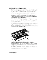
In the case of a power failure, after the printer has been switched off,
push the head by hand to the right until it reaches its end of stroke.
•
Whenever the color head is removed from the machine, take care to place
it in the "Service station "supplied with the color kit: this will ensure that
the head ink has the maximum protection against drying .
_______________________ Note: _________________________
If the computer is switched off while the printer is still switched on,
the printer will reset. If the printer is switched off during this reset, the
print head may not stop in its rest position.
Always switch off the printer before switching off the computer.
Summary of Contents for DECcolorwriter 520ic
Page 1: ...DECwriter 500i DECcolorwriter 520ic LJ500 and LJ520 Service Manual EK LJ50E SV A01...
Page 18: ......
Page 70: ......
Page 74: ......
Page 78: ......
Page 80: ...Electrical Interconnections 8 2 8 2 POWER SUPPLY BOARD...
Page 81: ...Electrical Interconnections 8 3 8 3 POWER SUPPLY CIRCUIT ON MAIN BOARD...
Page 84: ......


