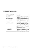
10.12 Handling the Optical Components
Table 10–1 Optical Cavity
Component
Description
Scan lens
The scan lens adjusts the scan to assure
correct linearity of the beam on the surface of
the drum.
Scanning assembly
The high-speed mirror causes the laser light
to scan through the scan lens.
Laser assembly
Generates an invisible beam of infrared light
and focuses the light onto the surface of the
scanning mirror.
Beam start mirror
The beam is reflected into the beam detect
lens by the beam start mirror. Slight
adjustment of this assembly causes a large
shift of the side-to-side registration, or
causes beam detect errors. For additional
information about beam detect errors, see the
SERVICE 51 entry in Table 6–5.
Warning:
Do not remove or adjust the beam
start mirror while in the field.
Beam detect
lens and fiber
optic connector
The lens focuses the beam into the fiber optic
cable. The detector on the DC control board
converts the light into the BD signal. The BD
signal causes the printer to feed paper and
send data.
10–26 Removal and Replacement Procedures and RSL


