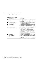
10.12 Handling the Optical Components
Use the following procedure to remove and replace the laser assembly:
Warning:
Use of procedures other than those specified here can result in
hazardous laser light exposure to yourself or to other persons in the room.
Before servicing the optical components, you must have attended the training
specified in Section D.1.
1. Make sure the power is off and the ac line cord is unplugged.
2. Remove the following components:
a. Upper cover, as shown in Section 10.2
b. Right and left side covers, as shown in Section 10.3
c. VCU, as shown in Section 10.20
d. DCU, as shown in Section 10.19
3. Disconnect the 7-pin J401 connector from the laser assembly. See the
following illustration to locate the correct two recessed screws.
Caution:
If you loosen the wrong screws, replace the laser assembly.
4. Remove the two recessed screws that hold the laser assembly to the optical
cavity.
5. Remove the laser assembly.
Removal and Replacement Procedures and RSL 10–29


