A.2 Macro Numbers
Table A–4 Device Identification
Device ID
Value
Digital ANSI-compliant
level 3 device
00
1
LN03
01
1
Factory default setting
A.2.1 Examples Using the Macro Feature
The examples in Table A–5 demonstrate how to determine the macro value.
Table A–5 Macro Feature Examples
Character Set
and Value
Initialization
Message
and Value
Device ID
and Value
Macro
Value
DEC 7-Bit Hebrew (50)
+
Disabled (00)
+
Level 3
(00)
=
50
DEC Technical (60)
+
Disabled (00)
+
Level 3
(00)
=
60
DEC Supplemental (00)
+
Disabled (00)
+
LN03 (01)
=
01
A.3 Interface Interconnections
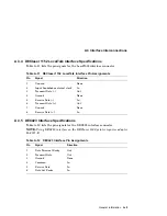
The DEClaser 1100 printer can connect to a host system through the 8-bit
parallel bus or through the serial connector. The term ‘‘port’’ is commonly used
when referring to the physical connector or to the software connection. You
select a port through the I/F (interface) display.
A.3.1 Parallel Port
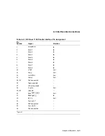
The parallel port uses a Centronics interface protocol and a 36-pin connector.
Table A–6 gives the pin numbers, signal names, and signal direction.
A–4 General Information


