A.3 Interface Interconnections
A.3.2 Serial Port
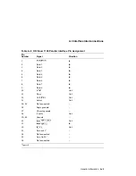
The serial port is EIA–232–D (RS232C) compatible and connects through a 25-
pin connector. Table A–8 lists the pin numbers, signal names, signal direction,
and wiring connections inside a null modem cable. Pin numbers that are not
mentioned are not used.
Note:
The pin out information presented here refers to equipment manufactured
by Digital only. For connection to other equipment, consult the manufacturer’s
documentation.
Table A–8 DEClaser 1100 Serial Interface
Printer
Pin
Signal
Name
Signal
Direction
Host Pin
Null Modem
1
Frame Ground (FG)
Not directional
Not applicable
2
Transmit Data (TD)
To host system
Pin 3
3
Receive Data (RD)
From host system
Pin 2
4
Request To Send (RTS)
To host system
5
6
Data Set Ready (DSR)
From host system
20
7
Signal Ground (SG)
Not directional
Not applicable
20
Data Terminal Ready (DTR)
To host system
6
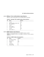
Table A–9 DEClaser 1152 Serial Interface
Pin
Signal
Direction
1
Not Used
None
2
Transmit Data
Out
3
Receive Data
In
4
Request to Send
Out
5
Clear To Send
In
6
Data Set Ready
In
7
Signal Ground
None
8-19
Not Used
None
20
Data Terminal Ready
Out
21-25
Not Used
None
General Information A–7


