1.9 LVPSA, Main Motor, and Interlock Diagram
1.9 LVPSA, Main Motor, and Interlock Diagram
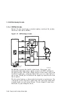
Figure 1–12 shows the major sections of the low-voltage power supply assembly
(LVPSA).
Figure 1–12 LVPSA Block Diagram
Power
Switch
Noise
Filter
Circuit
Breaker
CB
101
AC Controller
Fuse
F1
Noise
Filter
Recti-
fier
T1
Recti-
fier
+24 V Power
Supply
Switch
FSRDRV
+24 V
Recti-
fier
Recti-
fier
+5 V Power
Supply
+5 V
+12 V
LVPSA
MLO-006185
+12 V Power
Supply
Door
Switching
Circuit
Oscil-
lator
Fixing Roller
Heater Drive
Door
Switch
To Fixing
Roller Heater
The LVPSA consists of the following major components:
• DC regulators that supply 12-Vdc and 5-Vdc power
• High-current 24-Vdc regulator that drives the main motor
• Interlock door switches that are actuated by the door rod assembly and
open as the front door opens
• AC controller that connects to and distributes line power
• CB101 reset circuit breaker
• Fixing roller heater drive circuit
• Fuse (F1) is inside the LVPSA and not accessible
The fixing roller heater drive controls the current for the fixing heater. The
signal
is generated on the DC control board. See Section 1.10 for
more information about the fixing roller heater drive.
1–22 Physical and Functional Description


