1.10 Fixing Heater Control Circuit
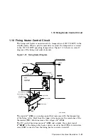
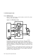
The TP1 and TP2 thermoswitches are mounted above the heat roller and
are in series with the heater element. If the temperature of the heat roller
goes too high, one or both of the thermoswitches will open. When the fixing
temperature cools, TP1 and TP2 should close.
A capacitor (not shown in Figure 1–13) on the DC control board keeps the error
message on the display and the fixing current off until the printer power has
been off for longer than 3 minutes.
The 50 SERVICE message is displayed if the fixing temperature:
• Fails to reach 50°C (122°F) within 40 seconds after power on.
• Fails to reach 100°C (212°F) within 40 seconds after reaching 50°C.
• Fails to reach 120°C (248°F) within 30 seconds after reaching 100°C.
• Fails to reach 140°C (284°F) within 30 seconds of receiving a print signal.
• If the temperature rises above 185°C (365°F).
• If the temperature drops below 90°C (194°F).
1–24 Physical and Functional Description


