C.2 Serial Interface Specifications
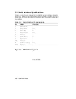
Table C–1 lists the pin signals for the RS232C serial interface connector.
Figure C–1 shows the pin assignments on the connector, while Figure C–2
and Figure C–3 show the serial connections with and without connection
to a modem.
Table C–1: Serial Interface Pin Assignments
Pin
Signal
Direction
1
Frame Ground
–
2
Transmit Data
Out
3
Receive Data
In
4
Request to Send
Out
5
Not Used
–
6
Data Set Ready
In
7
Signal Ground
–
8–19
Not Used
–
20
Data Terminal Ready
Out
21–25
Not Used
–
Figure C–1:
RS232C Pin Assignments
MLO-004884
C–4
Operator’s Guide
Summary of Contents for DEClaser 1100 Series
Page 18: ...Figure 1 1 Components Front Right Side View MLO 005960 1 2 Operator s Guide ...
Page 21: ...Figure 1 2 Components Rear Left Side View MLO 005961 Printer Components 1 5 ...
Page 23: ...Figure 1 3 Components Inside the Printer MLO 005962 Printer Components 1 7 ...
Page 31: ...2 Pull the extension tray straight out MLO 005815 Operating Information 2 5 ...
Page 34: ...3 Tap the stack of paper on a flat surface to align the edges MLO 005967 2 8 Operator s Guide ...
Page 65: ...Figure 3 1 Control Panel MLO 005830 3 2 Operator s Guide ...
Page 177: ...Figure C 2 Serial Connections to Modem MLO 004885 Specifications C 5 ...

