4.5.6 INTERFACE Menu
The correct interface connection is necessary for the printer to communicate
properly with the host computer. The DEClaser 1100 printer supports both
parallel and serial interface connections. The interface must match the
type used by the host computer.
You cannot make selections from the INTERFACE menu using commands
from the host computer. All values must be selected from the control panel
and can be saved only in NVRAM. Once you make the selections, you should
save them in NVRAM so that they will be activated (loaded into operational
memory) each time the printer is powered on. The INTERFACE menu
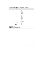
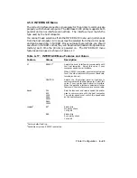
features and values are shown in Table 4–17.
Table 4–17: INTERFACE Menu Features and Values
Feature
Values
Description
i/f
RS232C
1
Selects the serial interface to communicate with
the host computer.
Select this value if your
computer uses a serial interface.
When RS232C is selected, you must select values
for all the other features in this menu (baud rate,
rsmode, and so on).
CENTRO
Selects the (Centronics) parallel interface to
communicate with the host computer. Select this
value if your printer uses a parallel interface.
When the parallel interface is selected, all other
features in the interface menu are not available.
baud
2
300
600
1200
2400
4800
1
9600
19200
Sets the transmit and receive speed the printer
uses to communicate with the host computer.
The printer speed must match the speed used
by the host computer.
rsmode
2
8S
1
8 data bits
No parity check
1 stop bit
8ES
8 data bits
Even parity check
1 stop bit
1
Factory default setting.
2
Available only when RS232C is selected.
Printer Configuration
4–23
Summary of Contents for DEClaser 1100 Series
Page 18: ...Figure 1 1 Components Front Right Side View MLO 005960 1 2 Operator s Guide ...
Page 21: ...Figure 1 2 Components Rear Left Side View MLO 005961 Printer Components 1 5 ...
Page 23: ...Figure 1 3 Components Inside the Printer MLO 005962 Printer Components 1 7 ...
Page 31: ...2 Pull the extension tray straight out MLO 005815 Operating Information 2 5 ...
Page 34: ...3 Tap the stack of paper on a flat surface to align the edges MLO 005967 2 8 Operator s Guide ...
Page 65: ...Figure 3 1 Control Panel MLO 005830 3 2 Operator s Guide ...
Page 177: ...Figure C 2 Serial Connections to Modem MLO 004885 Specifications C 5 ...


