4.5.5.3 Paint Mode (paint)
The paint mode (paint) feature instructs the printer to reserve memory
space for one or two full bitmap pages, or not to allocate any bitmapped
memory space for page printing. Since printer memory is shared with both
fonts and page drawings, it is usually desirable to let the printer allocate
the memory dynamically, because even full-page sixel images often print
in partial paint mode. You should enable the printer to direct the memory
allocation mechanism only in the following situations:
•
If you are receiving error messages about page complexity—for example,
21 COMPLEX DATA.
•
If pages are breaking incorrectly—for example, half the page prints on
one sheet and the second half on the next sheet.
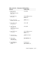
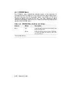
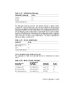
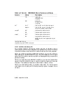
See Table 4–12 for a complete description of the paint mode values.
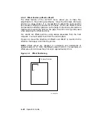
4.5.5.4 Paper Size (paper)
The paper size feature determines the printable area on the page. It is
only used in manual feed mode when no other command has been received
to specify paper size.
See Section 2.8 for additional information about
manually feeding media.
4.5.6 INTERFACE Menu
The correct interface connection is necessary for the printer to communicate
properly with the host computer. The DEClaser 2100 plus printer supports
both parallel and serial interface connections. The interface must match
the type used by the host computer.
You cannot make selections from the INTERFACE menu using commands
from the host computer. All values must be selected from the control panel
and can be saved only in NVRAM. Once you make the selections you should
save them in NVRAM so that they will be activated (loaded into operational
memory) each time the printer is powered on. The INTERFACE menu
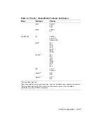
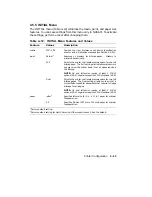
features and values are shown in Table 4–17 and described in the following
sections.
4–26
Operator’s Guide
Summary of Contents for DEClaser 2100 plus
Page 19: ...Figure 1 1 Components Front Right Side View MLO 004826 1 2 Operator s Guide...
Page 21: ...Figure 1 2 Components Rear Left Side View MLO 004827 1 4 Operator s Guide...
Page 23: ...Figure 1 3 Components Inside the Printer MLO 004828 1 6 Operator s Guide...
Page 39: ...5 Replace the cover on the cassette Fig 2 14 MLO 004840 Operating Information 2 13...
Page 44: ...2 Fold out the extension tray Fig 2 17 MLO 004836 2 18 Operator s Guide...
Page 48: ...14 Close the rear output tray Fig 2 21 MLO 004834 2 22 Operator s Guide...
Page 65: ...Figure 2 1 Engine Test Print Fig 2 40 MLO 004525 Operating Information 2 39...
Page 68: ...Figure 2 2 Test Print A Fig 2 42 MLO 004851 2 42 Operator s Guide...
Page 72: ...Figure 2 3 Test Print B Fig 2 43 MLO 004852 2 46 Operator s Guide...
Page 75: ...Figure 2 4 Font List Fig 2 44 MLO 004853 Operating Information 2 49...
Page 224: ...Figure C 2 Serial Connections to Modem MLO 004885 Specifications C 5...
Page 225: ...Figure C 3 Serial Connections Without Modem MLO 004887 C 6 Operator s Guide...


