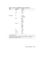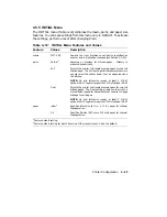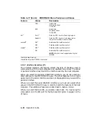
Table 4–17 (Cont.): INTERFACE Menu Features and Values
Feature
Values
Description
7OS
7 data bits
Odd parity check
1 stop bit
8SS
8 data bits
No parity check
2 stop bits
dtr
2
Fix-H
1
Sets the DTR line to a fixed high signal.
Ready-H
Sets the DTR line to a high signal when
the printer is ready to receive data.
xon/xoff
2
ON
1
Enables buffer overflow control.
OFF
Disables buffer overflow control.
etx/ack
2
OFF
1
Disables buffer overflow control.
ON
Enables buffer overflow control.
NOTE: Etx/ack is not supported on Digital
systems.
1
Factory default setting.
2
Available only when RS232C is selected.
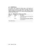
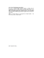
4.5.6.1 Interface Selection (i/f)
The interface selection (i/f) feature selects the type of interface used to
communicate with the host computer and enables video mode. The serial
or parallel interface must match the interface used by the host computer.
When you select the parallel (CENTRO) interface, you do not select any
other settings in the INTERFACE menu. The other features in this menu
apply only to the serial interface and are not displayed when you select the
parallel interface.
When you select the serial (RS232C) interface, you must also select other
values in the INTERFACE menu in order to match the features of the host
computer. The additional features are described in Section 4.5.6.2.
When you select Optional I/O, you enable video mode. You must plug the
video option into the I/O port for the Optional I/O option to appear on the
i/f menu.
4–28
Operator’s Guide
Summary of Contents for DEClaser 2100 plus
Page 19: ...Figure 1 1 Components Front Right Side View MLO 004826 1 2 Operator s Guide...
Page 21: ...Figure 1 2 Components Rear Left Side View MLO 004827 1 4 Operator s Guide...
Page 23: ...Figure 1 3 Components Inside the Printer MLO 004828 1 6 Operator s Guide...
Page 39: ...5 Replace the cover on the cassette Fig 2 14 MLO 004840 Operating Information 2 13...
Page 44: ...2 Fold out the extension tray Fig 2 17 MLO 004836 2 18 Operator s Guide...
Page 48: ...14 Close the rear output tray Fig 2 21 MLO 004834 2 22 Operator s Guide...
Page 65: ...Figure 2 1 Engine Test Print Fig 2 40 MLO 004525 Operating Information 2 39...
Page 68: ...Figure 2 2 Test Print A Fig 2 42 MLO 004851 2 42 Operator s Guide...
Page 72: ...Figure 2 3 Test Print B Fig 2 43 MLO 004852 2 46 Operator s Guide...
Page 75: ...Figure 2 4 Font List Fig 2 44 MLO 004853 Operating Information 2 49...
Page 224: ...Figure C 2 Serial Connections to Modem MLO 004885 Specifications C 5...
Page 225: ...Figure C 3 Serial Connections Without Modem MLO 004887 C 6 Operator s Guide...

