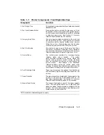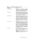
Table 1–3: Printer Components: Internal View
Component
Function
1. Print Density Dial
Has a range of 1–9 to adjust the print density.
Selecting the lower numbers results in heavier or
darker print density. For most printing applications
the dial can be set to 7. See Section 2.11 for additional
information about setting the print density.
2. Cleaning Brush
The (green) cleaning brush has two cleaning surfaces:
The brush end, which is used to clean the discharging
pins on the transfer corona assembly; and the fabric
end, which is used to clean the primary corona wire
in the EP-S cartridge.
See Chapter 7 for more
information about using the cleaning brush.
3. Fixing Assembly
The fixing assembly consists of a heat roller, a
pressure roller, and a roller cleaner. Toner is bonded
to the paper as it passes between the heat and
pressure rollers. The roller cleaner removes excess
toner that may accumulate on the heat roller. The
roller cleaner is replaced each time a new EP-S
cartridge is installed.
Each EP-S cartridge comes
with replacement instructions, or you can refer to
Section 7.3 for more information about replacing the
roller cleaner.
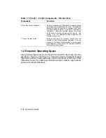
4. EP-S Cartridge
The EP-S cartridge contains a photo-sensitive drum,
the primary charge corona wire, a drum cleaning
blade, toner, and a toner application roller. When
the 16 TONER LOW message first appears, it could
mean that the toner is not being distributed evenly.
Rock the cartridge to redistribute the toner (see
Section 7.3).
If the 16 TONER LOW message
continues to be displayed after you rock the cartridge,
it means the EP-S cartridge has run out of toner and
you should replace it.
Each EP-S cartridge comes
with replacement instructions, or see Section 7.3 for
instructions if necessary.
5. Ozone Filter
Removes ozone generated by the printer. The ozone
filter is replaced every 100,000 pages. The page count
is shown on Test Print A (see Section 2.13).
See
Section 7.4 for replacement instructions.
WARNING: Do not operate the printer without the
ozone filter in place. The filter removes ozone that
could be hazardous to your health.
Printer Components
1–7
Summary of Contents for DEClaser 2100 plus
Page 19: ...Figure 1 1 Components Front Right Side View MLO 004826 1 2 Operator s Guide...
Page 21: ...Figure 1 2 Components Rear Left Side View MLO 004827 1 4 Operator s Guide...
Page 23: ...Figure 1 3 Components Inside the Printer MLO 004828 1 6 Operator s Guide...
Page 39: ...5 Replace the cover on the cassette Fig 2 14 MLO 004840 Operating Information 2 13...
Page 44: ...2 Fold out the extension tray Fig 2 17 MLO 004836 2 18 Operator s Guide...
Page 48: ...14 Close the rear output tray Fig 2 21 MLO 004834 2 22 Operator s Guide...
Page 65: ...Figure 2 1 Engine Test Print Fig 2 40 MLO 004525 Operating Information 2 39...
Page 68: ...Figure 2 2 Test Print A Fig 2 42 MLO 004851 2 42 Operator s Guide...
Page 72: ...Figure 2 3 Test Print B Fig 2 43 MLO 004852 2 46 Operator s Guide...
Page 75: ...Figure 2 4 Font List Fig 2 44 MLO 004853 Operating Information 2 49...
Page 224: ...Figure C 2 Serial Connections to Modem MLO 004885 Specifications C 5...
Page 225: ...Figure C 3 Serial Connections Without Modem MLO 004887 C 6 Operator s Guide...

