Appendix D
LN03 Compatibility
D.1
General Differences . . . . . . . . . . . . . . . . . . . . . . . . . . . . . . . .
D–1
D.2
Printable Area Compatibility . . . . . . . . . . . . . . . . . . . . . . . . .
D–2
D.3
Protocol Compatibility . . . . . . . . . . . . . . . . . . . . . . . . . . . . . .
D–2
Glossary
Index
Figures
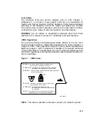
1
CDRH Label . . . . . . . . . . . . . . . . . . . . . . . . . . . . . . . . . . . . . .
xvii
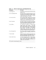
1–1
Components: Front/Right-Side View . . . . . . . . . . . . . . . . . . .
1–2
1–2
Components: Rear/Left-Side View . . . . . . . . . . . . . . . . . . . . .
1–4
1–3
Components: Inside the Printer . . . . . . . . . . . . . . . . . . . . . . .
1–6
1–4
Operating Space: Top View . . . . . . . . . . . . . . . . . . . . . . . . . .
1–9
1–5
Operating Space: Side View . . . . . . . . . . . . . . . . . . . . . . . . . .
1–9
2–1
Engine Test Print . . . . . . . . . . . . . . . . . . . . . . . . . . . . . . . . . . 2–39
2–2
Test Print A . . . . . . . . . . . . . . . . . . . . . . . . . . . . . . . . . . . . . . 2–42
2–3
Test Print B . . . . . . . . . . . . . . . . . . . . . . . . . . . . . . . . . . . . . . 2–46
2–4
Font List . . . . . . . . . . . . . . . . . . . . . . . . . . . . . . . . . . . . . . . . 2–49
3–1
Control Panel . . . . . . . . . . . . . . . . . . . . . . . . . . . . . . . . . . . . .
3–1
4–1
Sample of a Menu . . . . . . . . . . . . . . . . . . . . . . . . . . . . . . . . .
4–1
4–2
Menu Display . . . . . . . . . . . . . . . . . . . . . . . . . . . . . . . . . . . . .
4–5
4–3
Operating Memory . . . . . . . . . . . . . . . . . . . . . . . . . . . . . . . . .
4–7
4–4
Operational Flow Chart . . . . . . . . . . . . . . . . . . . . . . . . . . . . .
4–11
4–5
TEST PRINT A Verification . . . . . . . . . . . . . . . . . . . . . . . . . . 4–15
4–6
Offset Positioning . . . . . . . . . . . . . . . . . . . . . . . . . . . . . . . . . . 4–20
4–7
Offset Printout Samples . . . . . . . . . . . . . . . . . . . . . . . . . . . . . 4–21
5–1
Unacceptable Labels . . . . . . . . . . . . . . . . . . . . . . . . . . . . . . .
5–9
6–1
Paper Jam Areas . . . . . . . . . . . . . . . . . . . . . . . . . . . . . . . . . . 6–13
7–1
Rocking the EP-S Cartridge . . . . . . . . . . . . . . . . . . . . . . . . . . 7–20
C–1
RS232C Pin Assignments . . . . . . . . . . . . . . . . . . . . . . . . . . . .
C–4
C–2
Serial Connections to Modem . . . . . . . . . . . . . . . . . . . . . . . . .
C–5
vii
Summary of Contents for DEClaser 2100 plus
Page 19: ...Figure 1 1 Components Front Right Side View MLO 004826 1 2 Operator s Guide...
Page 21: ...Figure 1 2 Components Rear Left Side View MLO 004827 1 4 Operator s Guide...
Page 23: ...Figure 1 3 Components Inside the Printer MLO 004828 1 6 Operator s Guide...
Page 39: ...5 Replace the cover on the cassette Fig 2 14 MLO 004840 Operating Information 2 13...
Page 44: ...2 Fold out the extension tray Fig 2 17 MLO 004836 2 18 Operator s Guide...
Page 48: ...14 Close the rear output tray Fig 2 21 MLO 004834 2 22 Operator s Guide...
Page 65: ...Figure 2 1 Engine Test Print Fig 2 40 MLO 004525 Operating Information 2 39...
Page 68: ...Figure 2 2 Test Print A Fig 2 42 MLO 004851 2 42 Operator s Guide...
Page 72: ...Figure 2 3 Test Print B Fig 2 43 MLO 004852 2 46 Operator s Guide...
Page 75: ...Figure 2 4 Font List Fig 2 44 MLO 004853 Operating Information 2 49...
Page 224: ...Figure C 2 Serial Connections to Modem MLO 004885 Specifications C 5...
Page 225: ...Figure C 3 Serial Connections Without Modem MLO 004887 C 6 Operator s Guide...


