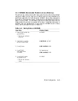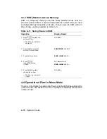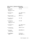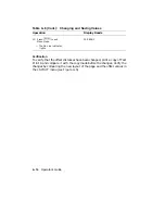
4.3.1 Operating Memory
The printer operates using the currently selected values contained in
operating memory. When the printer is powered on, it loads the values
stored in NVRAM into operating memory. When you select new values
(through escape sequences or from the control panel), they are placed in
operating memory and become part of the printer settings that are currently
in use. Figure 4–3 shows the operational flow between the different types
of memory.
Figure 4–3:
Operating Memory
ROM
NVRAM
RAM
Load<-ROM
Save->NVRAM
Power On
Printer
Save->RAM
Reset
Operating Memory
(Contains Current Printer Settings)
Commands
(Host Computer)
Menu Operations
(Control Panel)
ROM
NVRAM
RAM
Not Cleared at Power-Off (Cannot Be Changed)
Not Cleared at Power-Off (Can Be Changed)
Cleared at Power-Off (Can Be Changed)
MLO-004947
Printer Configuration
4–7
Summary of Contents for DEClaser 2100 plus
Page 19: ...Figure 1 1 Components Front Right Side View MLO 004826 1 2 Operator s Guide...
Page 21: ...Figure 1 2 Components Rear Left Side View MLO 004827 1 4 Operator s Guide...
Page 23: ...Figure 1 3 Components Inside the Printer MLO 004828 1 6 Operator s Guide...
Page 39: ...5 Replace the cover on the cassette Fig 2 14 MLO 004840 Operating Information 2 13...
Page 44: ...2 Fold out the extension tray Fig 2 17 MLO 004836 2 18 Operator s Guide...
Page 48: ...14 Close the rear output tray Fig 2 21 MLO 004834 2 22 Operator s Guide...
Page 65: ...Figure 2 1 Engine Test Print Fig 2 40 MLO 004525 Operating Information 2 39...
Page 68: ...Figure 2 2 Test Print A Fig 2 42 MLO 004851 2 42 Operator s Guide...
Page 72: ...Figure 2 3 Test Print B Fig 2 43 MLO 004852 2 46 Operator s Guide...
Page 75: ...Figure 2 4 Font List Fig 2 44 MLO 004853 Operating Information 2 49...
Page 224: ...Figure C 2 Serial Connections to Modem MLO 004885 Specifications C 5...
Page 225: ...Figure C 3 Serial Connections Without Modem MLO 004887 C 6 Operator s Guide...


