background image

 .  .  .  .  .  .  .  .  .  .  .  .  .  .  .  .  .  .  .  .  .  .  . 

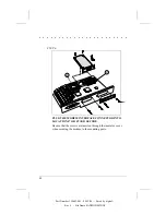
STEP 4

1

2

3

LOOSEN THE SCREWS AND REMOVE THE SYSTEM
CONTROLLER BOARD.

1   Thumbscrews
2   System Controller Board
3   Rear Cover

STEP 5

2

2

1

3

REMOVE THE BLANK PLATE COVERING AN
INTERFACE CONNECTOR SLOT.

1   Blank Plate
2   Mounting Posts
3   Retaining Bracket

11

Part Number 194683-001 - 08/12/94 - - Saved by digital - -

Rev #    - File Name FAXMODM2.DOC

Summary of Contents for DEClaser 3500

Page 1: ...EClaser 3500 Printer Internal Fax Modem Installation Guide EK D350P IG A01 Digital Equipment Corporation Maynard Massachusetts Part Number 194683 001 08 12 94 Saved by digital Rev File Name FAXMODM2 D...

Page 2: ...e from Digital or an authorized sublicensor Digital Equipment Corporation 1994 All Rights Reserved Printed in the U S A The following are trademarks of Digital Equipment Corporation DECimage Plus DECl...

Page 3: ...o frequency energy and if not installed and used in accordance with the instructions may cause harmful interference to radio communications However there is no guarantee that interference will not occ...

Page 4: ...ctor hoods in order to maintain compliance with FCC Rules and Regulations U S REGULATIONS GOVERNING THE USE OF FACSIMILE DEVICES This equipment complies with Part 68 of the FCC rules Located on the Fa...

Page 5: ...to maintain uninterrupted telephone service If you experience trouble with this telephone equipment contact your local telephone company for information on obtaining service or repairs The telephone...

Page 6: ...y an authorized Canadian maintenance facility designated by the supplier Any repairs or alternations made by the user to this equipment or equipment malfunctions may give the telecommunications compan...

Page 7: ...ore of the following grounding methods when handling or installing electrostatic sensitive parts n Use a flexible wrist strap with a minimum of 1 megohm 10 percent resistance in the ground cord that i...

Page 8: ...LLATION n Internal Fax Modem Option Kit n Nonmagnetic Phillips screwdriver CAUTION To avoid electrostatic damage to the printer option and or system controller board follow the safety precautions outl...

Page 9: ...querait de provoquer une d charge lectrique ou d endommager l imprimante AVVERTENZA Spegnere la stampante e staccare il cavo di alimentazione CA prima di rimuovere la scheda del controller del sistema...

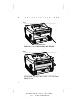
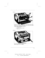
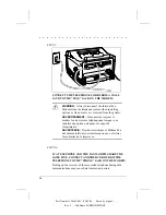
Page 10: ...STEP 2 DISCONNECT ALL CABLES FROM THE PRINTER STEP 3 PRESS DOWN ON THE TABS TO OPEN AND LOWER THE REAR COVER 10 Part Number 194683 001 08 12 94 Saved by digital Rev File Name FAXMODM2 DOC...

Page 11: ...BOARD 1 Thumbscrews 2 System Controller Board 3 Rear Cover STEP 5 2 2 1 3 REMOVE THE BLANK PLATE COVERING AN INTERFACE CONNECTOR SLOT 1 Blank Plate 2 Mounting Posts 3 Retaining Bracket 11 Part Number...

Page 12: ...CE CONNECTOR INTO LOCATION J7 OR J9 AND SECURE Be sure that the screws are inserted through the insulator cover when securing the modem to the mounting posts 12 Part Number 194683 001 08 12 94 Saved b...

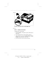
Page 13: ...ALL AND SECURE THE CONTROLLER BOARD AND CLOSE THE REAR COVER 1 Thumbscrews 2 System Controller Board 3 Rear Cover STEP 8 RECONNECT ALL CABLES 13 Part Number 194683 001 08 12 94 Saved by digital Rev Fi...

Page 14: ...nstallez une option ou d posez le capot de l imprimante ADVERTENCIA Desconecte siempre el M dem Fax del sistema telef nico al instalar opciones o al retirar las cubiertas de la impresora STEP 10 IF A...

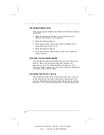
Page 15: ...he printer is placed offline and in menu mode 2 Go to the Reports menu to print a Hardware Report 3 After printing the report press Online En ligne Inlinea En l nea to place the printer back online 4...

Page 16: ...r Fax Modem option kit contains software to use with the Fax Modem Refer to the software package that contains your operating system for fax utility installation instructions If no Operation Guide is...

Reviews: