. . . . . . . . . . . . . . . . . . . . . . .
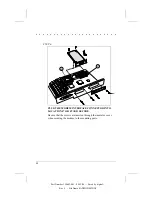
STEP 6
J9
J7
PLUG THE MODEM INTERFACE CONNECTOR INTO
LOCATION J7 OR J9 AND SECURE.
Be sure that the screws are inserted through the insulator cover
when securing the modem to the mounting posts.
12
Part Number 194683-001 - 08/12/94 - - Saved by digital - -
Rev # - File Name FAXMODM2.DOC

