background image

Troubleshooting 

Digital DECpc LP

44

MCS Logistics Engineering - Nijmegen

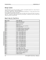
Beep Codes

If the POST finds an error and cannot display a message, the computer's speaker emits a series of beeps to
indicate the error and places a value in I/O port 80h.
For example, a failure of bit 3 in the first 64 KB of RAM is indicated by a 2-1-4 beep code (a burst of two
beeps, a single beep, and a burst of four beeps).
The table below lists the beep codes and the values the POST writes to I/O port 80h when it encounters a
fatal error.  This table lists fatal errors that lock up the computer.  Nonfatal errors that do not lock up the
computer are listed in a separate table.

Beep Codes for Fatal Errors

Beep Code

Error Message

1-1-3

CMOS write/read failure

1-1-4

ROM checksum failure

1-2-1

Interval timer failure

1-2-2

DMA failure

1-2-3

DMA page register write/read failure

1-3-1

RAM refresh failure

1-3-3

1st 64 KB RAM chip or data line failure

1-3-4

1st 64 KB RAM odd/even logic failure

1-4-1

1st 64 KB RAM address line failure

1-4-2

1st 64 KB RAM parity failure

2-1-1

Bit 0 1st 64 KB RAM failure

2-1-2

Bit 1 1st 64 KB RAM failure

2-1-3

Bit 2 1st 64 KB RAM failure

2-1-4

Bit 3 1st 64 KB RAM failure

2-2-1

Bit 4 1st 64 KB RAM failure

2-2-2

Bit 5 1st 64 KB RAM failure

2-2-3

Bit 6 1st 64 KB RAM failure

2-2-4

Bit 7 1st 64 KB RAM failure

2-3-1

Bit 8 1st 64 KB RAM failure

2-3-2

Bit 9 1st 64 KB RAM failure

2-3-3

Bit A 1st 64 KB RAM failure

2-3-4

Bit B 1st 64 KB RAM failure

2-4-1

Bit C 1st 64 KB RAM failure

2-4-2

Bit D 1st 64 KB RAM failure

2-4-3

Bit E 1st 64 KB RAM failure

2-4-4

Bit F 1st 64 KB RAM failure

3-1-1

Slave DMA register failure

3-1-2

Master DMA register failure

3-1-3

Master interrupt mask register failure

3-1-4

Slave interrupt mask register failure

3-2-4

Keyboard/mouse controller failure

4-2-1

Timer tick interrupt failure

4-2-2

Shutdown failure

Summary of Contents for DECpc LP

Page 1: ...Service Maintenance Manual DECpc LP PC K MN SD00000 21 JG00 A Copyright Digital Equipment Corporation All rights reserved March 1996 MCS LOGISTICS ENGINEERING NIJMEGEN THE NETHERLANDS...

Page 2: ...ication or disclosure by the U S Government is subject to restrictions as set forth in subparagraph c 1 ii of the Rights in Technical Data and Computer Software clause at DFARS 252 227 7013 Copyright...

Page 3: ...IVERS 16 CONFIGURING THE COMPUTER 17 Running the BIOS Setup Utility 17 BIOS SETUP UTILITY OPTIONS 18 CHAPTER 3 SERVICE PROCEDURES 23 SAFETY REQUIREMENTS 23 RECOMMENDED TOOLS Error Bookmark not defined...

Page 4: ...1 Diskette Drive Cabling Scheme 41 CHAPTER 4 TROUBLESHOOTING 43 INITIAL TROUBLESHOOTING 43 BEEP CODES 44 Beep Codes for Fatal Errors 44 Beep Codes for Non Fatal Errors 45 POST AND BOOT MESSAGES 45 COM...

Page 5: ...Locations 31 Figure 3 5 SIMM Socket Locations 33 Figure 3 6 Removing a 5 Inch FDD 34 Figure 3 7 Removing the HDD Mounting Tray 35 Figure 3 8 Removing the 3 Inch FDD 35 Figure 3 9 Removing the FDD Adap...

Page 6: ...Revision History MCS Logistics Engineering Nijmegen 7 Revision History Revision Date Description of Change Revision A01 March 96 First release of the Service Maintenance Manual describing the DECpc LP...

Page 7: ...ed since many of the diagnostic tests are designed to test more than one product CAUTION Digital recommends that only A certified engineers attempt to repair this equipment All troubleshooting and rep...

Page 8: ...g with a host of high performance options DECpc LP computers are the most advanced low profile desktop computers in their class All DECpc LP computers are industry standard Intel i486 PCs using a vers...

Page 9: ...ngineering Nijmegen Product Models Information DECpc LP Models Information Product Model FDD HDD Memory Cache Options DECpc 333sxLP PC734 xx DECpc 340dxLP PC736 xx DECpc 425sxLP PC741 xx DECpc 433dxLP...

Page 10: ...age of the advanced features of the computer s video circuitry Diskette 1 System and VGA Utilities This diskette contains the following files SETUP COM Allows to enable the ROM Base Setup option in th...

Page 11: ...desired video mode 8 Remove the backup copy and then reboot the computer so changes immediately take effect 9 If required install the operating system and any application software Running SETUP COM T...

Page 12: ...drive A and store it in a safe place KP EXE KP EXE is an MS DOS executable file that allows to set a password for the keyboard and mouse without turning off the computer When setting this password the...

Page 13: ...ter Diskette 1 Windows 3 0 3 1 Drivers This diskette contains a variety of Windows compatible video device drivers To install any of the supplied video device drivers do the following 1 Make sure the...

Page 14: ...utility enables to select and permanently store information about the computer s hardware and software in the battery backed memory of CMOS RAM This information takes effect each time the computer bo...

Page 15: ...d 49 are user definable for hard drives not listed in the BIOS drive table Caution It is essential to specify the correct IDE hard disk type because the main logic board s BIOS cannot independently ve...

Page 16: ...f Enables or disables the NumLock feature each time the computer boots Password Not Installed Installed Enables or disables a power on password Parallel port Enabled at 378h 37Ah IRQ7 278h 27Ah IRQ7 3...

Page 17: ...nd 3 or types 48 and 49 to be user definable Drive type 48 or 49 information is aliased to drive type 2 or 3 when application software does not recognize drive types above 47 Auto detection of IDE dri...

Page 18: ...Note Enabling the secondary cache significantly improves computer performance by reducing the average number of wait states seen by the microprocessor However in some instances you might want to disab...

Page 19: ...Keep circuit boards and components away from non conductors Keep clothing away from circuit boards and components Keep circuit boards in anti static bags Be cautious when AC power is exposed when work...

Page 20: ...erials Cleaning agent should be an all purpose cleaner that is used in house Required Special Tools None Remedial Diagnostic Test Software QAPLUS fe PC Advanced Diagnostic Software latest version Part...

Page 21: ...Information BIOS version information Refer to the Digital DECpc Bulletin Board Support for the latest information on BIOS upgrades Network locations North America South America Australia and New Zeal...

Page 22: ...e following 1 Turn off power to all external devices connected to computer 2 Turn computer off 3 Unplug power cord from wall outlet 4 Disconnect power cord and monitor cord from computer To remove the...

Page 23: ...Digital DECpc LP Service Procedures MCS Logistics Engineering Nijmegen 27 Computer Components Figure 3 2 LP Computer Model Components...

Page 24: ...fingers can result in permanent damage to electronic components DECpc 3xx 4xx LP Main Logic Board Jumper Settings Settings shown in bold italics are valid for the Cornerstone ImageAccel controllers F...

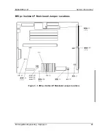
Page 25: ...Digital DECpc LP Service Procedures MCS Logistics Engineering Nijmegen 29 DECpc 3xx 4xx LP Main board Jumper Locations Figure 3 3 DECpc 3xx 4xx LP Mainboard Jumper Locations...

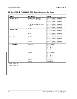
Page 26: ...and 3 jumpered J102 pins 2 and 3 jumpered J103 pins 2 and 3 jumpered Processor type 1 486DX 486SX J114 pins 1 and 2 jumpered J115 pins 1 and 2 jumpered J114 pins 2 and 3 jumpered J115 pins 2 and 3 jum...

Page 27: ...Digital DECpc LP Service Procedures MCS Logistics Engineering Nijmegen 31 DECpc 450D2LP 466D2LP CPU Board Jumper Locations Figure 3 4 DECpc 450D2LP 466D2LP CPU Board Jumper Locations...

Page 28: ...make sure to Install 36 bit SIMMs having an access time of 70 ns or less Only those configurations listed below are allowed 4 MB or 16 MB single in line memory modules SIMMs may be added Fill bank 0 b...

Page 29: ...Digital DECpc LP Service Procedures MCS Logistics Engineering Nijmegen 33 SIMM Socket Locations Figure 3 5 SIMM Socket Locations...

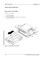
Page 30: ...ics Engineering Nijmegen Removal Procedures Removing a 5 Inch FDD To remove a 5 Inch FDD 1 Turn off the computer 2 Remove outside cover 3 Remove two retaining screws from each side of bottom bay 4 Rem...

Page 31: ...ernal devices ac power and monitor power 3 Unlock and remove outside cover 4 Disconnect power and ribbon cables 5 Remove the HDD mounting tray to access the FDD retaining screws 6 Remove the four FDD...

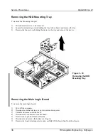
Page 32: ...ding the device to the tray and remove the device Figure 3 10 Removing the HDD Mounting Tray Removing the Main Logic Board To remove the main logic board 1 Turn off the computer 2 Disconnect external...

Page 33: ...nections Legend Description A Video connector B Parallel port C Serial port 2 D Serial port 1 E Keyboard connector F Mouse connector G Power connector H Battery I Floppy disk interface J IDE hard disk...

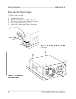
Page 34: ...he power supply 1 Disconnect power cord 2 Disconnect all of the power supply connectors 3 Pull off the remote ON OFF mechanical connector 4 Remove the six PSU retaining screws 5 Slide the PSU backward...

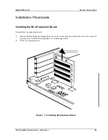
Page 35: ...ling the Bus Expansion Board To install the bus expansion board 1 Position the Bus Expansion Board above the socket on the main board and slide it into the connector you may have to tilt the board sli...

Page 36: ...gs 2 Turn off the computer 3 Unlock and remove outside cover 4 Disconnect the battery cable from header BATTERY CONN on the main logic board 5 Remove battery from its mounting pad located on the main...

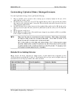
Page 37: ...installed mass storage devices diskette or IDE is an addition to the computer or a different type NOTE Make sure the cable is connected with correct orientation Most cables and sockets are keyed so t...

Page 38: ...Follow these general procedures to troubleshoot the DECpc LP computer Press Ctrl Alt Del If the computer fails to boot turn it off wait until all hard disk drives spin down completely and then turn i...

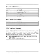
Page 39: ...register write read failure 1 3 1 RAM refresh failure 1 3 3 1st 64 KB RAM chip or data line failure 1 3 4 1st 64 KB RAM odd even logic failure 1 4 1 1st 64 KB RAM address line failure 1 4 2 1st 64 KB...

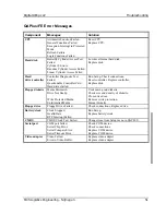
Page 40: ...Screen retrace or failure POST and Boot Messages The POST displays messages to alert to errors in hardware software and firmware or to provide operating information about the computer Each time the PO...

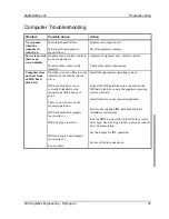
Page 41: ...640 KB base memory 0 KB extended memory Time of day clock stopped Replace RTC Invalid configuration information Run the BIOS Setup utility Diskette drive failure Run the BIOS Setup utility Check all...

Page 42: ...ftware is not installed on the IDE hard disk drive IDE hard disk drive is not correctly formatted or the requested partition does not exist There is no software on the requested partition IDE hard dis...

Page 43: ...d SCSI hard disk drive kit installation instructions Refer to the supplied SCSI hard disk drive kit installation instructions on setting SCSI IDs Remove terminating resistors Refer to the supplied kit...

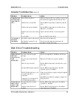
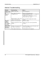
Page 44: ...oard port Disk Drive Troubleshooting Problem Possible Cause Action IDE SCSI hard disk drive cannot read or write information Incorrect disk drive jumper settings Loose or incorrectly installed cables...

Page 45: ...ure the computer for VGA operation Set the jumper for VGA operation Refer to Main Logic Board Jumpers Adjust the monitor brightness and contrast controls Distorted rolling or flickering screen display...

Page 46: ...etup Check connections Reset controller Replace controller Replace disk Floppy diskette Media Mismatch Drive Not Ready Write Protected Media Unformatted Media Use known good diskette Check size and de...

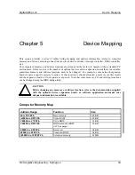
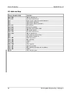
Page 47: ...work expansion boards require a specific memory location If that location is already allocated a memory conflict results and the expansion board will not operate as expected Note that some memory I O...

Page 48: ...r 82C496 82C497 040 043 Interval timer 060 06F Keyboard controller 070 07F Real time clock RTC NMI 080 08F DMA page register 0A0 0A1 Interrupt controller two 0C0 0CF DMA controller two 0F0 Clear math...

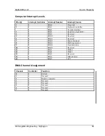
Page 49: ...2 IRQ8 Real time clock RTC 4 2 IRQ9 Reserved 5 2 IRQ10 Reserved 6 2 IRQ11 Reserved 7 2 IRQ12 Mouse interrupt 8 2 IRQ13 Math coprocessor 9 2 IRQ14 Hard disk drive 10 2 IRQ15 Reserved 11 1 IRQ3 COM2 12...

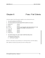
Page 50: ...ts Hard Disk all tests except Sequential write read destructive test and Sequential write random read destructive test Floppy Disk all tests Keyboard all tests COM Ports all tests LPT Ports all tests...

Page 51: ...Digital DECpc LP Service Notes MCS Logistics Engineering Nijmegen 59 Appendix A Service Notes This appendix contains the service notes for the DECpc LP series computer...

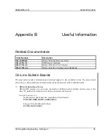
Page 52: ...rds The most current product information and technical support is also available on line The most current device drivers Setup diskettes and technical tips can be found on all of these bulletin boards...

Page 53: ...to make this document a valuable support to your service efforts for Digital Please fill out the reader feedback form and send or fax it to Digital Equipment Parts Center b v Att MCS Logistics Enginee...

Page 54: ...m are used at Digital s direction Did you find errors in this manual If so specify by page What is your general reaction to this manual format completeness organisation etc Is the documentation unders...

Reviews: