4-16
(5) Printing mechanism replacement
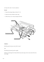
Removal
1.
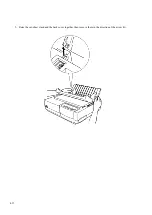
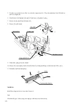
Remove the tractor unit (Section 4.9.1 (2)) and covers (Section 4.9.1 (3)).
2.
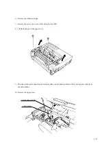
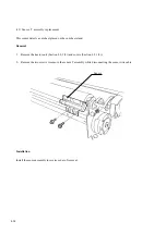
Remove the two screws.
3.
Steadying the printing mechanism, disconnect the six connectors from the printer control board:
Print head cables: CNHEAD1, CNHEAD2, CNHEAD3
Line feed motor wire cables: CNLF
Space motor wire cable: CNSP
Sensor wire cable: CNDET
4.
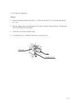
Remove the printing mechanism.
Installation
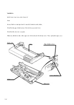
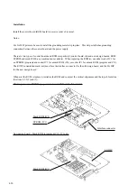
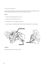
Install the printing mechanism in reverse order of removal.
Notes:
Be sure to connect all connectors to the control board.
Use cable clamps for the line feed motor, space motor, and sensor cables.
Put the tractor paper-end sensor cable in the recess of the bottom cover.
The sensor cable must not hang over the bottom feed slot of the bottom cover.
The SP motor cable and the LF motor cable must not touch the transistor elements on the control board so that
cables can not be caught between the control board and the bottom of the mechanism.
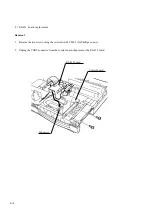
Printer control board
Printing mechanism
Summary of Contents for LA30 N
Page 1: ...Order Number ER LA30N SV 003 Service Manual TM LA30N LA30W Companion Printer...
Page 2: ......
Page 5: ......
Page 39: ...3 16...
Page 91: ......
Page 137: ......
Page 140: ......
Page 141: ...TM Printed in Ireland...


