4-20
Installation
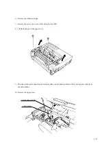
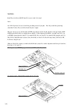
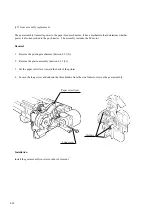
Install the control board (ROM board) in reverse order of removal.
Notes:
For LA30W printers, be sure to install the grounding metal strip in place. This strip establishes grounding
connection between the control board and the power supply.
There are two types of control boards and ROMs respectively (control board: old and new design boards, ROM:
EPROM and mask ROM; any combinations available). When replacing the ROM(s), use either socket IC1 for
an EPROM (program) and socket IC3 for a mask ROM (CG) or socket IC1 for a mask ROM (program and CG).
The ROM’s orientation mark (cut) must face the interface connector for the old design board, and the LG HIC
for the new design board.
Whenever the ROM is replaced, initialize the ROM and re-adjust the vertical alignment and the top-of-form line.
(Sections 4.9.2 (2) and (3)).
Interface connector
Old design board + EPROM (program) and mask ROM (CG): IC1 and IC3
EPROM (IC1)
Mask ROM (IC3)
New design board + Mask ROM (program & CG): IC1 only
Mask ROM (IC1)
LG HIC
Summary of Contents for LA30 N
Page 1: ...Order Number ER LA30N SV 003 Service Manual TM LA30N LA30W Companion Printer...
Page 2: ......
Page 5: ......
Page 39: ...3 16...
Page 91: ......
Page 137: ......
Page 140: ......
Page 141: ...TM Printed in Ireland...

