4-25
(13) Carriage unit replacement
Removal
1.
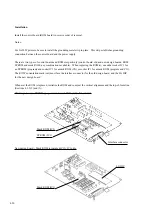
Remove the printing mechanism (Section 4.9.1 (5)), SP motor (Section 4.9.1(11)), and print head (Section
4.9.1 (14)).
2.
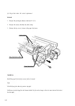
Mark the setting positions of the adjustment levers R and L at both sides of the mechanism. (For adjustment
lever R, see the figure on the next page.)
3.
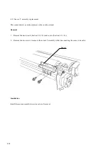
Loosen the screw to remove the plate spring.
4.
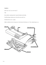
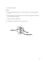
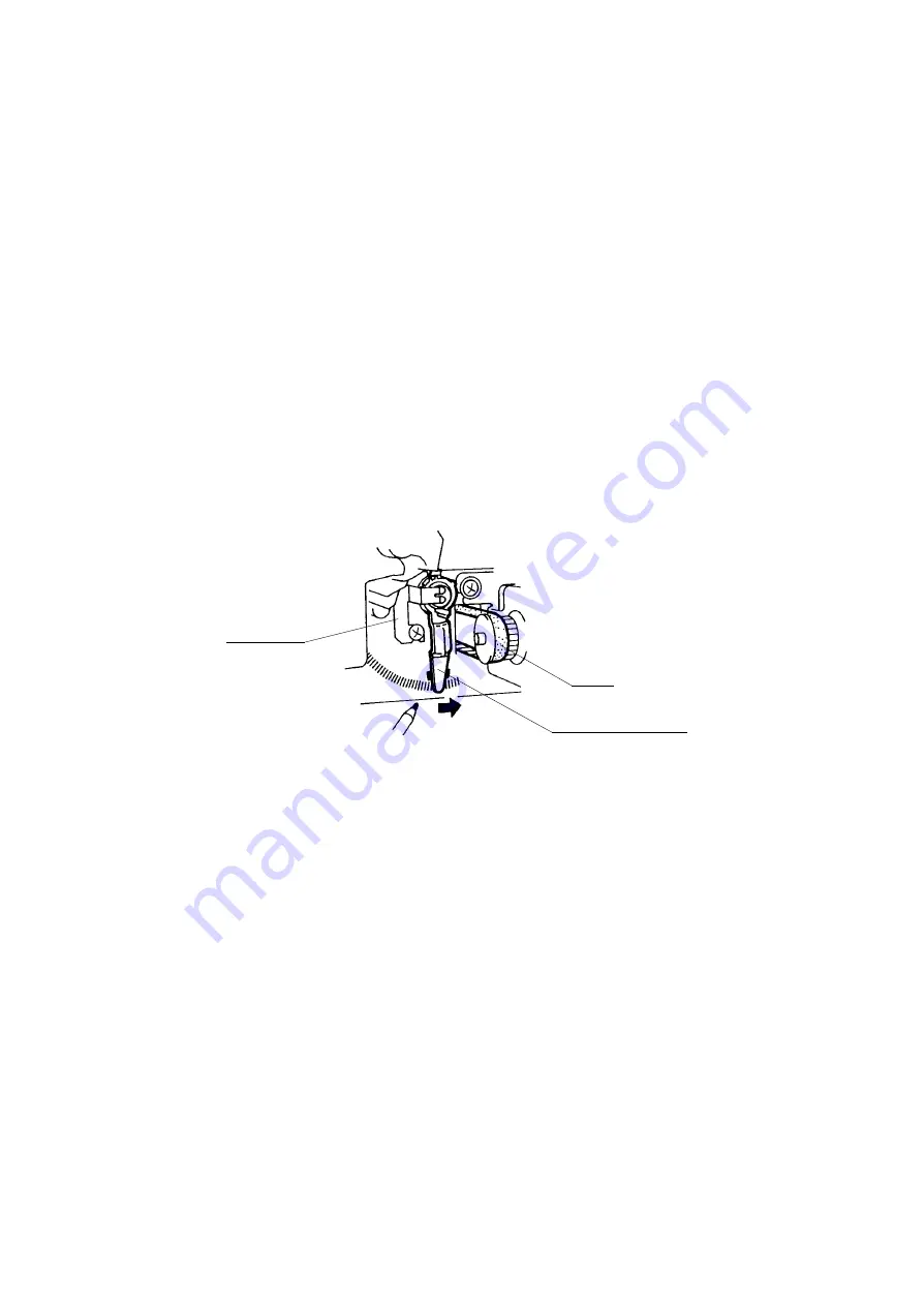
Turn adjustment lever L counterclockwise until it contacts the belt (A).
Adjustment lever L
Belt
Plate spring
A
Summary of Contents for LA30 N
Page 1: ...Order Number ER LA30N SV 003 Service Manual TM LA30N LA30W Companion Printer...
Page 2: ......
Page 5: ......
Page 39: ...3 16...
Page 91: ......
Page 137: ......
Page 140: ......
Page 141: ...TM Printed in Ireland...


