background image

Mounting the Push Tractor Unit in Front Position

Warning:

The printer must be powered-off before you start this procedure.

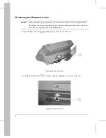
1. Remove the Push tractor unit 

 from its plastic packet.

2. Remove the black plastic protection 

 from the electrical connector 

.

3. Disengage the plastic protection 

 from the feeding motor gear wheel, rotating it as shown in

the picture.

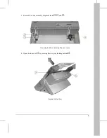
d4001a04

4

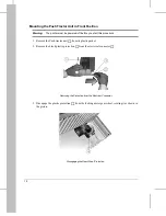
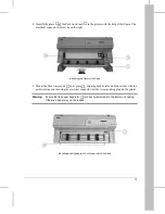
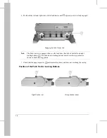
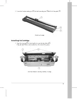
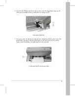
Disengaging the Gear Wheel Protection

1

2

3

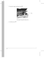
d4001a02

Removing the Protection from the Electrical Connector

12

Summary of Contents for LA400plus

Page 1: ...User Guide DIGITAL Matrix Printer LA400plus Order Number EK LA45E UG 001 1...

Page 2: ......

Page 3: ...Digital Matrix Printer LA400plus Setting Up Your Printer Digital Equipment Corporation Maynard Massachusetts...

Page 4: ...thout the prior written permission of Digital Equipment Corporation 1998 All rights reserved The following are trademarks of Digital Equipment Corporation LA400plus MultiPrinter and the Digital logo C...

Page 5: ...aper Path for Continuous Forms 11 Feeding Cut Sheets and Envelopes 11 Mounting the Push Tractor Unit in Front Position 12 Position of the Push Tractor Locking Buttons 14 Step 3 Starting up the Printer...

Page 6: ...ur Host System 33 Connecting your Printer to a PC Environment 34 Connecting to the PC 34 Checking the Protocol 35 What s a Protocol 35 Setting the Protocol 35 Installing the Windows Printer Driver 36...

Page 7: ...your printer Digital Environment There are no specific requirements since your DIGITAL Matrix Printer LA400plus is a Digital printer especially designed and manufactured for perfect integration in the...

Page 8: ...your printer Step 1 Unpacking the Printer Step 2 Mounting the Push Tractor Unit Step 3 Starting up the Printer Step 4 Selecting the Display Language Step 5 Installing the Black Ribbon Cartridge Step...

Page 9: ...ht Avoid dusty dirty or humid environment Work Location Choose a flat stable surface near to the host system or PC Avoid obstructing the openings of the casing located on both side of the casing for c...

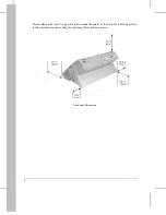
Page 10: ...We recommend that you free up some space around the printer as shown in the following picture to allow automatic paper routing for continuous form and easy access Free Space Dimensions 4...

Page 11: ...IGITAL Matrix Printer LA400plus 5 Push tractor unit 2 Power cable 6 Black ribbon cartridge 3 Setting Up Your Printer User Guide 7 Serial interface cable 4 Printer driver disk Windows 3 1 and Windows 9...

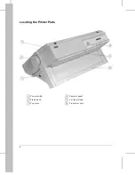
Page 12: ...Locating the Printer Parts 1 Power switch 4 Operator panel 2 Platen knob 5 Cut sheet stand 3 Top cover 6 Front slot cover 1 2 3 4 5 6 d400 c02 6...

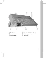
Page 13: ...7 Rear slot cover 0 Slot for optional Set Up card or font card 8 Power socket Pull tractor mechanism covers 9 Interface connectors Large rear cover 7 8 0 9 d400 c03 7...

Page 14: ...em in case you have to transport the printer relocate it or return it to Digital Services for maintenance 1 Open the front slot cover by pulling it up at the center of the cover 2 Lock the front slot...

Page 15: ...Remove the basic assembly shipment locks and 4 Open the top cover by pressing the two gray locking buttons 2 3 4 d4001c06 Removing the Basic Assembly Shipment Locks 6 5 d4001c07 Opening the Top Cover...

Page 16: ...5 Remove the carriage motor shipment lock 6 Close the top cover 7 d4001c08 Removing the Carriage Motor Shipment Lock 10...

Page 17: ...unit standard the Pull tractor unit option You can mount the feeding devices in two positions the Front position under the front slot cover the Rear position under the rear slot cover The most common...

Page 18: ...ush tractor unit from its plastic packet 2 Remove the black plastic protection from the electrical connector 3 Disengage the plastic protection from the feeding motor gear wheel rotating it as shown i...

Page 19: ...both its left and bottom sides with the printer casing and inserting the electrical connector into the corresponding plug on the printer Warning Ensure that the paper separator is correctly retracted...

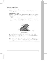
Page 20: ...h left and right locking buttons The Push tractor locking buttons must be in the up position as shown in the following picture 7 Check that the paper separator seats inside the printer and does not ov...

Page 21: ...r outlet supplies the voltage indicated on the electrical data plate on the left side of the printer when facing the operator panel above the power switch If the electrical data plate indicates a diff...

Page 22: ...call your dealer Do NOT attempt to change the plug yourself 2 Make sure the printer is powered off The power switch is in the O position 3 Plug the power cable into the power socket at the back of the...

Page 23: ...er is detected by the printer the printer beeps the Fault indicator is on and the indicator for the Push Front paper path blinks slowly indicating the paper path where paper should be loaded If any fa...

Page 24: ...anguage Selecting the Language To select the language 1 Press the Set Up button The message MACROS appears on the display and the Set Up indicator blinks slowly 2 Press the R button The message INSTAL...

Page 25: ...ration To permanently save your choice in the current M1 macro press the Sel Save button The new language selection will still be active at next power on To temporarily save your choice press the Exit...

Page 26: ...ons to see how to install the color ribbon cartridge 1 Remove the black ribbon cartridge from its plastic packet 2 Turn the ribbon feed knob in the engraved arrow direction to take up slack in the rib...

Page 27: ...n guide Installing the Cartridge 1 Open the top cover by pressing the two gray locking buttons The print head moves automatically to the center of the printer 6 5 7 d400 b43 The Ribbon Cartridge 2 1 3...

Page 28: ...front mounting pin turn the ribbon feed knob of the cartridge according to the engraved arrow until the mounting pin is in contact with the cartridge support See the following picture 4 Align the cen...

Page 29: ...and the print head guide 6 Position the back mounting pins on the back locking grooves of the cartridge supports 7 Push down the ribbon cartridge above the mounting pins area so that the pins fully e...

Page 30: ...e print head along the carriage bar Caution This operation can be done only when you are installing the ribbon cartridge for the first time If you have been already printing and you are going to repla...

Page 31: ...t be powered off before beginning with this procedure Loading the Paper Note Your DIGITAL Matrix Printer LA400plus is factory set to have the left tractor already positioned for the first printing col...

Page 32: ...e the door of the left tractor and if necessary adjust the position of both paper supports along the tractor bar to get equal intervals between them and the edges of the paper 3 4 2 d4001a10 Installin...

Page 33: ...If necessary move the right tractor along the tractor bar to position its pins in front of the pinfeed holes of the paper Place the pinfeed holes on the same tractor pins as on the left tractor so tha...

Page 34: ...g both tractors 7 Once the paper is properly positioned lock the left tractor on the tractor bar by pushing up its locking lever and if necessary adjust the right tractor position so that the paper is...

Page 35: ...its edges are aligned with the printer casing 11 Press the FF Load button The message Loading paper appears on the display and the paper is automatically loaded into the printer When the paper stops t...

Page 36: ...to enter Set Up mode The display shows MACROS 3 Press the R button three times until the display shows TEST HEX DUMP 4 Press the D button The display shows Self test 5 Press the Sel Save button The p...

Page 37: ...Self Test Printout 31...

Page 38: ...face you need a modular 6 pin DECconnect type connector This cable is supplied with the printer package 1 Make sure the printer is switched off The power switch is at the position O 2 Insert the inter...

Page 39: ...EED SIGNAL AUTOFEED signal setting Disabled SLCT IN SIGNAL SELECT IN signal setting Disabled DISCON ON FAULT Disconnect on fault No discon WORD LENGTH Number of bits per byte 8 bit BAUD RATE Transfer...

Page 40: ...s not supplied with the printer package but can be supplied by your dealer 1 Make sure the printer is switched off The power switch is at the position O 2 Insert the interface cable into the parallel...

Page 41: ...ning Factory Setting PROTOCOL PARAL Parallel interface protocol EPSON ESC P2 INTERFACE TYPE Interface type Automatic Switching between parallel and serial port is automatic PARALLEL MODE Communication...

Page 42: ...the Printer Driver disk Printing a Test Page Printing a Test Page under Windows 3 x Follow the procedure below in order to print a test page 1 Power the printer on The Fault indicator blinks 2 Press...

Page 43: ...Digital Matrix Printer LA400plus User Guide Digital Equipment Corporation Maynard Massachusetts...

Page 44: ......

Page 45: ...nal View 2 3 The Ribbon Cartridge 2 4 The Black Ribbon Cartridge 2 4 The Push Tractor Unit 2 5 The Push Tractor Unit in Front Position 2 6 The Push Tractor Unit in Rear Position 2 7 The Operator Panel...

Page 46: ...h Tractorin Front Position 3 10 Mounting the Push Tractor Unit in Front Position 3 10 Loading the Paper 3 13 Removing the Push tractor Unit from Front Position 3 19 Handling Continuous Forms using the...

Page 47: ...ettings for Paper Thickness 5 5 Managing Blank Pages 5 5 Printing on Pre printed Forms 5 6 Adjusting theTop of Form from the Operator Panel 5 6 Quickly Switching between Two Paper Types 5 7 6 Configur...

Page 48: ...Setting the Parallel Interface 6 19 Parallel Mode 6 19 AUTOFEED Signal 6 19 SELECT IN Signal 6 20 Setting the Serial Interface 6 20 Disconnection on Fault 6 20 Word Length 6 20 Baud Rate 6 20 Parity...

Page 49: ...aper Position Definition 7 13 Setting the DEC Mode 7 15 Horizontal Pitch 7 15 G0 Character Set 7 16 User Preference Character Set 7 17 Printer ID 7 17 Wrap or Truncate 7 18 Disconnection on EOT 7 18 I...

Page 50: ...the Ribbon Cartridge 10 2 How to Replace the Ribbon Cartridge 10 2 Transporting the Printer 10 3 11 Troubleshooting Installation Problems and Solutions 11 1 Printing Problems and Solutions 11 2 Paper...

Page 51: ...l Characteristics Technical Specifications B 1 Paper Specifications B 4 Print Area B 4 Paper Thickness B 6 C LCD Display Messages Simple messages C 1 User Instructions C 1 Status Messages C 2 Operatin...

Page 52: ...tails using the table of contents and chapter introductions to locate specific information This part has several appendixes and an index Appendix A lists supplies and options available form your deale...

Page 53: ...s made possible by the removable Push tractor unit that can be installed in Front or Rear position With the optional additional Push tractor unit you can then use at the same time either the Push Fron...

Page 54: ...has been manufactured to withstand factory floor environments and heavy duty applications One remarkable characteristic of your printer is in its 400 million characters print head life This is twice...

Page 55: ...from the printer The automatic Interface Type selection permits you to integrate your printer into a heterogeneous environment and to share it using its dual interface You can define four customized p...

Page 56: ......

Page 57: ...r This chapter describes the major parts and controls of your DIGITAL Matrix Printer LA400plus To find out how to assemble connect and set up your printer see the Setting Up Your Printer section at th...

Page 58: ...7 8 9 0 d400 c03 1 2 3 4 5 6 d400 c02 d4003b20 Getting to Know Your Printer 2 2...

Page 59: ...o control the printer 5 Cut sheet stand for the Manual paper path 6 Front slot cover for the Push Front paper path Rear and Right View 7 Rear slot cover for the Push Rear paper path 8 Large rear cover...

Page 60: ...Matrix Printer LA400plus can use either a black ribbon or a color ribbon if the color mechanism is installed see section Preparing for Color Printing in Appendix A Supplies and Options The black ribbo...

Page 61: ...device used to load continuous form into the printer According to your needs the Push tractor unit can be mounted in Front position or in Rear position 1Connector cover 4Tractor door 2Connector 5Tract...

Page 62: ...Step 6 Loading Continuous Form in the Setting Up Your Printer section you find at the beginning of this guide The Push tractor unit installed in the Front position feeds the paper from the front slot...

Page 63: ...Rear position is described in Chapter 3 Handling Different Types of Paper of this User Guide With the Push tractor unit in this position the paper is fed through the rear entry slot and is ejected th...

Page 64: ...printing functions and the operating state of the printer You use the buttons to control the printer The indicator lights show you which function mode or Paper Path is selected or give information abo...

Page 65: ...host and the current print tasks are put on hold Ready Ready blinking The printer is in Pause state and there is still data in the input buffer Set Up Set Up off The printer is in normal state Set Up...

Page 66: ...it option You can mount the feeding devices in two positions the Front position under the front slot cover the Rear position under the rear slot cover Caution Always remember to power off the printer...

Page 67: ...have chosen See the following section to know the states and modes definitions The main function of each button is related to the Normal mode This function is printed above the button in a shaded rect...

Page 68: ...rinted being printed or not No fault is detected by the sensors Pause Printing is put to hold No fault is detected by the sensors Fault A fault is detected by the sensors The printer buzzer sounds acc...

Page 69: ...ar bar at the end of the print task or see the last printed line when you switch to Pause state Set Up This mode mainly allows you to set up your printer according to your operating environment You ca...

Page 70: ...g the Print Noise Level in Chapter 4 Same as for Ready Pause state Same as for Ready Pause state Inactive Macro To select one of the Macros access to the M1 M2 M3 and M4 button functions See Using Mac...

Page 71: ...M4 To select Macro 4 See Using Macros in Chapter 4 Pause To toggle between the Pause and the Ready state The paper moves according to the settings of the Tear View mode See Holding a Print Task in Cha...

Page 72: ...irmware version of your printer and the list of set up features of the four macros and their associated values Note This function is no longer active once you enter Set Up See Printing the Printer Con...

Page 73: ...ous item See How to Configure Your Printer in Chapter 6 Sel Save To select a Value and save the new Configuration See How to Configure Your Printer in Chapter 6 Exit To exit Set Up mode without saving...

Page 74: ...the Top of Form Value to zero D To reduce the Top of Form Value the paper moves backwards accordingly See Adjusting the Top of Form from the Operator Panel in Chapter 5 U To increase the Top of Form...

Page 75: ...arts the printer state the Lock symbol selected Macro and the current Protocol Printer State Message Meaning Ready The printer is in Ready state Busy The printer is in Busy state Pause The printer is...

Page 76: ...is selected Aut blinking The interface type is set to automatic The printer switches to the protocol you selected for each type of interface serial or parallel when receiving data Hex The Hexadecimal...

Page 77: ...s Common Meaning SoftContrl Soft Software Control Draft 10 Software Control means that the font and the pitch that are used by the printer are defined through the commands of your software application...

Page 78: ...rmation on the printer status Example Top cover open This message reminds you that the top cover is open or at least not correctly closed The Operating Messages These interactive messages are displaye...

Page 79: ...re and humidity conditions and the performance of the paper may be adversely affected due to extremes in these conditions To prevent damage paper envelopes and cards should be stored in the original p...

Page 80: ...y tested prior to regular use Envelopes Envelopes should be tested prior to use The minimum length of the envelopes that can be inserted through the manual entry slot is 4 102 mm Note For the Paper Sp...

Page 81: ...it installed in the rear position The paper is input into the printer through the rear tractor paper slot and is output through the rear paper slot Note With an additional Push tractor unit two contin...

Page 82: ...ded from the front and fed with the Pull tractor unit option Push Pull One fanfold paper loaded using both the Pull tractor unit Option and the Push tractor unit installed in Front position Path b The...

Page 83: ...n Value Definition From Macro The paper path at power on will be the paper path selected in the active Macro at power on The corresponding PAPER PATH Option is available in the Macro Option list only...

Page 84: ...e new selected path is out of paper the corresponding indicator blinks The printer will load the paper corresponding to your new paper path selection only when receiving data Tips on Selecting the Pro...

Page 85: ...may be incompatible with printing on preprinted forms Program listings Multiparts with chemical or carbon paper Adhesive labels with TEAR VIEW MODE set to No tear reverse Paper driving reliability Not...

Page 86: ...Best paper routing Sheet by sheet feeding Allows printing on paper without any option mounted Adhesive Labels Paper Path Paper Type Document Type Advantages Disadvantages Pull According to paper spec...

Page 87: ...ll Width 3 to 17 76 to 432 mm 3 to 17 76 to 432 mm 3 to 17 76 to 432 mm Length 3 to 24 76 to 609 mm 3 to 24 76 to 609 mm 3 to 24 76 to 609 mm Thickness max 0 025 0 5 mm max 0 014 0 3 mm max 0 025 0 5...

Page 88: ...er off the printer 1 Remove the Push tractor unit from its plastic packet 2 Remove the black plastic protection from the electrical connector 3 Disengage the plastic protection from the feeding motor...

Page 89: ...nto the corresponding plug on the printer and aligning both its left and bottom sides with the printer casing Warning Ensure that the paper separator is correctly retracted in the tractor unit casing...

Page 90: ...ght buttons The Push tractor locking buttons must be in the up position as shown in the following picture 7 Check that the paper separator seats inside the printer and does not overhang the casing Pos...

Page 91: ...show the installation of 80 column paper 1 Position the paper stack in front of the printer as shown in the following figure and make sure that the paper can be fed freely into the printer 2 Open the...

Page 92: ...rvals between them and the edges of the paper 4 Open the door of the right tractor then to facilitate placing paper on the tractor pins unlock the tractor by pushing down its locking lever 6 2 5 d4001...

Page 93: ...in front of the pinfeed holes of the paper Place the pinfeed holes on the same tractor pins as on the left tractor so that the top edge of the paper is parallel to the tractor bar 3 6 d400 a13 Positi...

Page 94: ...f you do not position the paper to print on the first printable column do not forget to adjust the LEFT MARGIN Option in Set Up mode Note When you aligning the paper edge with the green mark on the pr...

Page 95: ...8 Lock the right tractor on the tractor bar by pushing up its locking lever Caution Do not stretch the paper too tightly The side perforation may tear or the pinfeed holes may enlarge and cause misfee...

Page 96: ...ush Front path at the operator panel 13 Press the FF Load button The message Loading paper appears on the display and the paper is loaded into the printer When the paper stops the Push Front indicator...

Page 97: ...ing the Set Up button followed by the Park button 2 Power off the printer 3 Open the left and right tractor doors and remove the paper 4 Press the tractor unit locking buttons down on both sides to un...

Page 98: ...4 Close the gear protection rotating it upwards 5 Close the front cover 4 d4002a04 Closing the Gear Protection Handling Different Types of Paper 3 20...

Page 99: ...ng any paper feeding device power off the printer Mounting the Push Tractor in Rear Position 1 Remove the large rear cover 2 Take the rear slot cover at the center and remove it 1 d4001c20 Removing th...

Page 100: ...correct insertion direction of the Push tractor the electric connector must be on the left and the tractor grooves face down 1 d4001c22 Repositioning the Large Rear Cover d4005a56 6 5 7 Orientating th...

Page 101: ...and hear the click of both left and right buttons The Push tractor locking buttons must be in the up position as shown in the following picture Position of the Push Tractor Locking Buttons 5 d4001a51...

Page 102: ...erefore not be necessary The following photos show how to load 80 column paper 1 Position the paper stack behind the printer and make sure that the paper can be fed freely into the printer 2 Lift the...

Page 103: ...and place the pinfeed holes of the paper on the tractor pins Close the door of the left tractor Note It is useful to insert the paper about 1 cm inside the rear slot as shown in the figure in order t...

Page 104: ...the pins in front of the pinfeed holes of the paper 5 Place the pinfeed holes 7 on the same tractor pins 8 as on the left tractor so that the top edge of the paper is parallel to the tractor bar Clos...

Page 105: ...o not position the paper to print on the first printable column you must adjust the LEFT MARGIN Option in Set Up mode Note When you align the paper edge with the green mark on the printer casing the l...

Page 106: ...supports Lock the right tractor Caution Do not stretch the paper too tightly The side perforation may tear or the pinfeed holes may enlarge and cause misfeed Make sure that the paper is taut by movin...

Page 107: ...lay and the paper is loaded into the printer When the paper stops the Push Rear indicator is on the Fault indicator is off and the display shows Ready M1 Aut You are now ready to print d4001a16 Paper...

Page 108: ...h tractor unit by pressing the Set Up button followed by the Park button 2 Open the left and right tractor doors and remove the paper 3 Push down the left and right locking buttons and pull the tracto...

Page 109: ...4 Mount the rear slot cover again by pushing it down into place 3 d4001a57 Installing the Rear Slot Cover Handling Different Types of Paper 3 31...

Page 110: ...ve paper If you select the No tear reverse Value for the TEAR VIEW MODE Option the parking function is inhibited Unsuccessful Paper Parking If the paper is not totally parked paper still inserted in t...

Page 111: ...the Manual paper path Note The Manual paper path is always available as soon as you insert a sheet The path is automatically selected and the sheet is loaded Loading Cut Sheets 1 Open the Cut sheet s...

Page 112: ...third large mark This position allows you to print the first column against the left side of the printable area no left margin If you do not position the paper to print on the first printable column...

Page 113: ...Note Be careful not to fold the sheet 4 Insert the sheet in the slot until it stops against the paper feed rollers Carefully follow the paper guides d4001a37 Inserting the Cut Sheet 4 d4001c27 Adjusti...

Page 114: ...the first printable line according to Set Up settings Note It is not necessary to select the Manual paper path before inserting the sheet The selection is performed automatically by the printer Eject...

Page 115: ...splayed 5 Press the D button to pass over to the Values for the Tear View mode 6 Press the R or L button until No tear reverse is displayed 7 Press the Sel Save button to set confirm the new setting A...

Page 116: ...pitch FF Load Advances the paper depending on the setting of the TEAR VIEW MODE Option See Chapter 6 Configuring Your Printer Note Use only the platen knob to recover from paper jams Always reset the...

Page 117: ...ost automatic way possible We assume that the TEAR VIEW MODE Option is set to one of the Auto advance Values For more information about managing the viewing of the last printed line see Chapter 7 Cust...

Page 118: ...pter 7 Customizing Macros To advance the paper for tearing off during a print task 1 Press the Pause button The printer finishes printing the current line The paper is fed so that the last printed lin...

Page 119: ...you also have to adapt the entire printer configuration by selecting other parameters defining the interface the installation the user adjustments etc For the DIGITAL Matrix Printer LA400plus such pa...

Page 120: ...3 seconds press the M1 M2 M3 or M4 button corresponding to the Macro you want to use The printer initializes the Values of the Macro the display shows Processing The basic screen then indicates the ne...

Page 121: ...acing contrast of the print out the printer behaviour blank pages management DEC mode management See Chapter 7 Customizing a Macro for more details By using a printer driver This technique reduces the...

Page 122: ...nd To select a resident font 1 Press the Font button 2 Within 3 seconds press the Font button until the desired font is displayed keeping the button depressed displays the different fonts continuously...

Page 123: ...layed keeping the button depressed displays the different pitches continuously Three seconds after releasing the button the display shows the basic screen again and the pitch is set Note If a pitch is...

Page 124: ...the Load X message where X is the current Paper Path 1 Make sure that paper is loaded in the current paper path 2 Press the FF Load button The display shows Loading paper and paper is loaded Note If n...

Page 125: ...ccording to your needs The corresponding Options are the following FORM LENGTH LEFT MARGIN FORM WIDTH TOP MARGIN BOTTOM MARGIN TOP OF FORM See Chapter 7 Customizing a Macro for a complete description...

Page 126: ...position it at the same position when a form feed occurs Top line This is the line where the printing actually starts To define a top margin select the number of this line Example In the following pi...

Page 127: ...3 1 2 TOF ABCDEFGHIJ ABCDEFGHIJ L 5 TOF 1 2 3 4 5 6 7 8 4 48 49 50 51 ABCDEFGHIJ ABCDEFGHIJ ABCDEFGHIJ 1 2 3 4 5 6 Print Area Definition Printing 5 3...

Page 128: ...The PRINT GAP Option defines the distance between the print head and the platen If you set the automatic adjustment Auto adjust Value for the print gap the printer senses the paper thickness each time...

Page 129: ...adjust Value of the PRINT GAP Option does not allow very precise print gap adjustment and should be used only for special paper when other settings have not produced satisfactory results Note For more...

Page 130: ...g if you decide to permanently save your setting Proceed as follows 1 Press the Set Up button 2 Press the Top of Form button The printer loads the paper in the current paper path The display shows the...

Page 131: ...aper for more information about selecting a paper path Paper handling is further enhanced with the optional additional tractor unit By mounting simultaneously the two tractor units on your printer you...

Page 132: ...ent kinds of print tasks INSTALLATION This Function contains generic parameters such as the language used for the display INTERFACE This Function lets you define the interface type and to set the comm...

Page 133: ...unction Level Options Level Sub options Level Values Level Macro Protocol Protocol Serial DEC PPL2 IBM XL24E EPSON ESC P2 Protocol Parallel DEC PPL2 IBM XL24E EPSON ESC P2 Font Draft Hi Draft Vertical...

Page 134: ...ble Values which generate immediate operations The Different Types of Selectable Values Three types of selectable Values have been defined according to how they are saved Value Type Meaning Factory Th...

Page 135: ...Functions Options Sub options and Values defining the entire Configuration Note In the Value list the Factory setting is shown in bold Macros Installation Interface Test Hex Dump User Access User Adju...

Page 136: ...ine 1 Front X 60 inches Line 1 Rear X 60 inches Tear Perfo Align X 60 inches Save Save Config Restore Macro X Rest all Macros Recall Factory Macros Macro 1 Macro 2 Macro 3 See pages 6 6 6 7 Installati...

Page 137: ...4 inches 15 inches Number of Lines X lines 1 to 256 Top of Form 0 60 inches 0 60 to 127 60 Paper Path Push Front Push Rear Manual Print Direction Unidirectional Bidirectional Soft Control Line Mode LF...

Page 138: ...9 See page 6 10 Language English Deutsch Espa ol Italiano Fran ais Error Buzzer 1 beep 3 beeps Continuous beep No beep Path at Power on From Macro Last sel Path DEC Mode Horizontal Pitch G0 Character...

Page 139: ...16 5 cpi 17 1 cpi 20 cpi Prop Spacing 18 cpi DEC Swiss DEC Portuguese Legal DEC Supplement DEC Spec Graph DECTechnical DEC 7Bit Hebrew DEC Hebrew Sup DEC Greek Sup DEC 7Bit Turk DEC Turk Sup JIS Kata...

Page 140: ...Page 853 Code Page 855 Code Page 857 Code Page 860 Code Page 861 Code Page 862 Code Page 863 Code Page 864 Code Page 865 Code Page 866 Code Page 869 Abicomp Brazilian ASCII Mazowian Code MJK Bulgarian...

Page 141: ...ge 862 Code Page 863 Code Page 864 Code Page 865 Code Page 866 Code Page 869 Abicomp Brazilian ASCII Mazowian Code MJK Bulgarian ISO 8859 7 ISO Latin 1T New Hebrew D Hebrew Code Page Code Page 210 Cod...

Page 142: ...d Rate 600 bps 1200 bps 2400 bps 4800 bps 9600 bps 19200 bps 38400 bps Parity Bit None Even Odd Buffer Control XON XOFF XON XOFF DTR DTR Robust XON No Yes Interface Type Automatic Parallel Serial I F...

Page 143: ...ecting a Configuration Value When you reach a Value selectable or not press the Sel Save button to select it or to perform the corresponding action Saving the new Configuration When you have finished...

Page 144: ...D button The display shows Draft 7 Press the R or L button until the display shows Orator 8 Press the Sel Save button to select this font An asterisk is displayed to indicate that the Value has been...

Page 145: ...Set Up button 2 Press the Print button The printer prints the current printer Configuration See the figure on the next page Note Values that are not applicable are printed in italic style Depending on...

Page 146: ...he title bar identifies the current Macro 5 Power on Values of the INSTALLATION Function 6 Power on Values of the USER ADJUSTMENTS Function 7 Power on Value of the USER ACCESS Function 8 Power on Valu...

Page 147: ...the current Macro only become its current Values Column CURRENT VALUES of the Configuration Sheet Restoring a Macro To overwrite the current Values of the current Macro with the corresponding power on...

Page 148: ...LANGUAGE Option to set the desired language Value Definition English English language Deutsch German language Espa ol Spanish language Fran ais French language Italiano Italian language Error Buzzer...

Page 149: ...ettings before selecting values for the printer interface Note Factory settings are shown in bold Interface Type Determines the type of interface to be used Value Definition Parallel The parallel inte...

Page 150: ...data exchange between the printer and the host for the parallel interface Value Definition Bidirectional The parallel interface uses the IEEE 1284 bidirectional standard mode Select this Value to tak...

Page 151: ...does not change Yes DTR drop The DTR line is dropped to low signal level Yes DTR pulse The DTR line is pulsed to high signal level with a 5 sec pulse Word Length The WORD LENGTH Option allows you to d...

Page 152: ...Definition DTR The DTR control regulates the data flow to the input buffer using DTR high DTR low voltage signals XON XOFF The XON XOFF control codes are used to regulate the data flow XON XOFF DTR Bo...

Page 153: ...o all Set Up items You can use all the operator panel buttons Macros You can only access the MACROS and SAVE Functions You can use all the operator panel buttons Test Hex Dump You can only access the...

Page 154: ...ry settings are shown in bold You access the following options using the MACRO Function and the corresponding MACRO X Option in Set Up mode Selecting the Protocol You have to set the printer protocol...

Page 155: ...g for Macro 2 and 4 when selecting the parallel protocol EPSON ESC P2 Sets the EPSON ESC P2 protocol to communicate with host software This is the Factory setting for Macro 1 and 3 when selecting the...

Page 156: ...printer and which area you want to define for printing Form Length The FORM LENGTH Option allows you to set the physical form length in inches or in number of lines Even if the logical definition of...

Page 157: ...nt value of the LEFT MARGIN Option is set to Column 1 each time you change the value of the HORIZONTAL PITCH Option This new setting applies only for the corresponding protocol Top Margin The TOP MARG...

Page 158: ...with a given Macro Remember that you can also select the paper path you want using the operator panel buttons Note This Option is available only if the PATH AT POWER ON Option of the INSTALLATION Func...

Page 159: ...ectional and the Bidirectional settings apply to both alphanumeric and graphics printing Line Mode The LINE MODE Option defines printer behaviour when receiving a carriage return or a line feed comman...

Page 160: ...The PRINT IMPACT Option determines the strength of the print head needles impact You can set this impact to a stronger impact for example when printing on multipart form to ensure that all the copies...

Page 161: ...5 parts For 6 parts The print gap is set according to the number of parts of your multipart paper Manual adjust The print gap is manually adjusted with the print gap selection knob See the correspondi...

Page 162: ...enter letting you access to the print gap selection knob behind and at the left of the left cartridge support The print gap is set at the maximum 4 Turn the print gap selection knob with your index fi...

Page 163: ...d 8 Perforation Anti jam The PERFO ANTI JAM Option can be enabled for paper with specially large perforation which can cause paper jams The use of this Option is necessary only for exceptional cases F...

Page 164: ...n Paper Position Definitions Value Definition Auto advance 1s Auto advance 2s Auto advance 3s Auto advance 4s Auto advance 5s Setting one of these Values the paper is automatically moved to the tear o...

Page 165: ...ed Currently Printing Without final FF With final FF Position State Position State Position State 1 Ready 2 Ready Busy 1 Pause 4 Pause 5 Pause 4 Pause 2 FF Load 5 Pause 6 Pause 5 Pause 3 Pause 2 Ready...

Page 166: ...nition Position Definition 1 Print head on last printed character while printing or at next line at the end of a job 2 Print head on first next Top of Form 3 Print head on second next top of form Cust...

Page 167: ...Position Definition 4 Viewing position Last printed line facing the tear bar 5 Tear off position Next perforation facing the tear bar 6 Second perforation facing the tear bar Customizing Macros 7 14...

Page 168: ...gin DISCONNECT EOT Determines whether a communication line disconnection occurs at the end of data transmission INIT REPORT Determines if an initialization report is sent to the host or not AUTO ANSWE...

Page 169: ...n DEC Norw Dan DEC Norwegian Danish DEC Swedish DEC Swedish DEC Dutch DEC Dutch DEC Swiss DEC Swiss DEC Portuguese DEC Portuguese DEC Supplement DEC Supplemental DEC Spec Graphi DEC Special Graphics D...

Page 170: ...l DEC Greek Suppl DEC Greek Supplemental ISO Latin 1 ISO Latin 1 ISO Latin 2 ISO Latin 2 ISO Latin 5 ISO Latin 5 ISO Lat Hebrew ISO Latin Hebrew ISO Lat Greek ISO Latin Greek ISO Lat Cyril ISO Latin C...

Page 171: ...right margin The exceeding text is lost See the following figure Disconnection on EOT The DISCONNECT EOT Sub option determines whether the communication disconnect occurs at the end of the transmissio...

Page 172: ...printer during initialization or not Value Definition Enabled An ANSWERBACK message is sent during initialization Disabled No ANSWERBACK message is sent during initialization ANSWERBACK on ENQ The ANS...

Page 173: ...de PITCH COMPRESS Determines the character pitch when receiving the COMPRESS command SLASHED ZERO Determines whether the zero character is printed with or without a slash Horizontal Pitch The HORIZONT...

Page 174: ...Page 855 Cyrillic Code Page 857 Turkish Code Page 860 Portugal Code Page 861 Icelandic Code Page 862 Hebrew Code Page 863 Canada France Code Page 864 Arabic Code Page 865 Denmark Norway Code Page 866...

Page 175: ...formed at 20 cpi Slashed Zero The SLASHED ZERO Sub option selects whether the zero character is printed with or without a slash Value Definition Yes Zero character is printed with a slash No Zero char...

Page 176: ...tion identifies which national character set is to use Value Definition USA USA France France Germany Germany United Kingdom United Kingdom Denmark 1 Denmark 1 Denmark 2 Denmark 2 Sweden Sweden Italy...

Page 177: ...855 Cyrillic Code Page 857 Turkish Code Page 860 Portugal Code Page 861 Icelandic Code Page 862 Hebrew Code Page 863 Canada France Code Page 864 Arabic Code Page 865 Denmark Norway Code Page 866 Russi...

Page 178: ...haracter sets are not altered Italic The Italic style is applied to the character set Slashed Zero The SLASHED ZERO Sub option selects whether the zero character is printed with or without a slash Val...

Page 179: ......

Page 180: ...utton MACROS is displayed 2 Press the R button three times TEST HEX DUMP is displayed 3 Press the D button 4 Pressing the R or the L button you can choose which test you want to perform Sub option Def...

Page 181: ...long the whole carriage bar For this reason the Self Test should always be performed with 136 columns wide paper to avoid damaging the platen The Self Test printout starts as soon as you press the Sel...

Page 182: ...ol To disable Hex Dump mode 1 Press the Set Up button The display shows Disable Hex D 2 Press the Sel Save button The printer switches back to Normal mode The basic screen is displayed Initializing th...

Page 183: ......

Page 184: ...Press the R or L button until the display shows USER ADJUSTMENTS 3 Press the D button The display shows BIDI ALIGNMENT 4 Press the R or the L button to scroll the Options of the USER ADJUSTMENTS Funct...

Page 185: ...ton The Bidirectional Alignment table is printed The current bidirectional offset Value is printed under the header For each possible Value two lines of pipe characters are printed 3 Select the desire...

Page 186: ...responding position 2 Display the desired Value and press the Sel Save button The printer parks the paper loads it again and prints the current Value at the actual corresponding position The paper is...

Page 187: ...loaded to the current tear off position The current Value is displayed 3 Press the R or L button to adjust the Tear off position The paper moves according to the displayed Value 4 When the paper perfo...

Page 188: ...to maintain it always in its best condition If the printer faults such as paper jam or other mechanical malfunctions become more often it is useful to vacuum the parts of the printer where dust and p...

Page 189: ...the print quality starts to become poor the ribbon cartridge must be changed The ribbon cartridge life is 15 million characters for the black ribbon and 2 million characters for each band of the colo...

Page 190: ...your printer pack it into its original packaging to avoid damage Follow the unpacking instructions in Step 1 of the Setting Up Your Printer section in reverse order Note Do not forget to install the...

Page 191: ......

Page 192: ...er switch in I on position Power cable damaged Check the power cable itself Printer failure Call Service Printer not printing Incorrect setting of the printer 1 Perform a self test Ready indicator lit...

Page 193: ...bbon cartridge type is not correct Use a Digital ribbon cartridge See Supplies and Options Order Numbers in Appendix A Ribbon is not properly installed Reinstall or readjust the ribbon cartridge prope...

Page 194: ...cation Interface in Chapter 6 Poor alignment of the vertical lines Bidirectional alignment setting is not correct 1 Perform the BIDI ALIGNMENT procedure of the USER ADJUSTMENTS Function 2 Check the re...

Page 195: ...Selection of the protocol is not correct Check the PROTOCOL Option setting in Set Up See Selecting the Protocol in Chapter 7 Printer communication settings are not appropriate to host settings Check t...

Page 196: ...unit are not positioned evenly across the paper width 1 Clear paper jam 2 Reinstall the paper Print head is too close to the paper Check the PRINT GAP Option setting in Set Up See Setting the Printing...

Page 197: ...th sensor and the manual path sensor 3 In case the Remove paper message is still displayed 4 Power off the printer 5 Make sure no paper is loaded 6 Hold down the Set Up button while powering the print...

Page 198: ...p Mode If the printer prints wrong characters you can select the Hex Dump Mode in the printer Test Hex Dump menu in order to analyze both printing and non printing characters arriving on the printer I...

Page 199: ......

Page 200: ...inuous forms on your printer The installation and use is the same as for the standard Push tractor unit Note See the section Quickly Switching between two Paper Types in Chapter 5 Printing Pull Tracto...

Page 201: ...ed with the Push Front path Specific routing needs the optional Pull tractor Great choice Simple part First part of the paper cannot be printed This paper path may be incompatible with printing on pre...

Page 202: ...the Pull Tractor Unit 1 Power the printer off 2 Remove the large rear cover 3 Remove the rear slot cover 1 d4001c20 Removing the Large Rear Cover 2 d400c21 Removing the Rear Slot Cover Supplies and Op...

Page 203: ...cover 5 Open the top cover and unhook the Pull tractor mechanism covers on the left and the right side 3 4 d4001b25 Unhooking the Pull Tractor Pins Covers 1 d4001c22 Repositioning the Large Rear Cove...

Page 204: ...the Pull tractor unit and the two cut out Pull tractor pins covers from the plastic packet d400a40 4 Removing the Left Pull Tractor Mechanism Cover 3 5 6 d400a56 The Pull Tractor Unit and its two Cut...

Page 205: ...l it clicks in place Repeat the same operation for the right cut out Pull tractor pins cover 9 Remove the black plastic protection from the electrical connector 9 0 d4001a46 Removing the Black Plastic...

Page 206: ...electric connector on the left and mount it on the printer pressing it down until it clicks Note Let the Push tractor unit in front position to facilitate paper loading 5 d4002a51 0 5 Installing the P...

Page 207: ...ding Continuous Forms using the Push Front Paper Path in Chapter 3 Handling Different Types of Paper 3 Press the FF Load button The paper is loaded to the Pull tractor and the message 1 Paper Pull 2 P...

Page 208: ...ned with the paper path direction Align the pinfeed of the Pull tractor unit with the paper pinfeed holes by moving the tractor bar with your fingers 2 d4001a60 Opening the Right Tractor 2 d4001a58 Op...

Page 209: ...ce the pinfeed holes of the paper on the tractor and close the door 8 Move the right tractor place the paper on it and close the door 4 d4001a52 2 Placing the Paper on the Left Tractor 2 d4004c29 Plac...

Page 210: ...r Push Pull The Factory setting is Pull The printer is now ready to print If you press Path you can force the path selection according to your needs Pull or Push Pull Then press Pause The printer is r...

Page 211: ...ost you need to configure only one printer How to Initialize the Set Up Card Before the Set Up Card can be used it is necessary to initialize it in the same way as you format a PC diskette This operat...

Page 212: ...l between the following Values Value Definition Printer Card The contents of the card is copied into printer permanent memory Printer Card The contents of the printer permanent memory is copied onto t...

Page 213: ...ing message SET UP CARD MODE for 5 seconds Then the display shows Printer Card 3 Press the Sel Save button The display shows Copying and the Printer Card Value is displayed again 4 You can then select...

Page 214: ...dge The color ribbon cartridge is slightly different from the black ribbon cartridge 1 Take the cartridge out of its plastic bag 2 Turn the ribbon feed knob to take up slack 1 Casing 4 Plastic bracket...

Page 215: ...inning with this operation make sure that the print head is not hot 1 Unpack the color mechanism from its carton Be careful to check that there are two screws 2 Check that the printer is powered on 3...

Page 216: ...connector of the print head Plug it pushing it with the help of the screwdriver 6 Put the color mechanism assembly on the carriage assembly d400b26 3 Inserting the Color Mechanism Connector 4 3 d400b2...

Page 217: ...7 Fix the color mechanism using the two screws 8 Close the top cover d400b34 7 Fixing the Color Mechanism on the Carriage Assembly Supplies and Options A 18...

Page 218: ...n 2 Open the top cover The print head moves automatically to the center of the printer 3 Locate the front locking grooves of the left and right cartridge supports 1 2 d4001b20 Opening the Top Cover 3...

Page 219: ...that the left mounting pin is in contact with the locking grooves 6 Slide the ribbon guide down onto the print head nose so that the ribbon is inserted between the print head nose and the print head...

Page 220: ...ver the mounting pins 8 Turn the ribbon feed knob to take up the ribbon slack 9 Insert the plastic bracket on the black guide of the color mechanism d4001b30 Locking the Ribbon Cartridge 0 Inserting t...

Page 221: ...10 Push the plastic bracket it down until it clicks 11 Close the top cover d4001b36 0 Pushing Down the Plastic Bracket Supplies and Options A 22...

Page 222: ...over The print head moves to the center of the printer 3 Unlock the plastic bracket by pushing on the click 4 Pull the plastic bracket off the color mechanism 1 d4002b32 Unlocking the Plastic Bracket...

Page 223: ...r Ribbon Cartridge 2 Million characters life per band LA40R KC Options Options Order Number Color Mechanism LA40X CX Push tractor unit LA40X PT Pull tractor unit LA40X PL Parallel interface cable 10 f...

Page 224: ...ad 17 225 Spread 10 275 Print Matrix Draft Quality 10 cpi 12 h x 24 v 36 h x 24 v 12 cpi 10 h x 24 v 30 h x 24 v 15 cpi 8 h x 24 v 24 h x 24 v Print Densities Horizontal Pitch cpi Characters for a 8 l...

Page 225: ...Epson Protocol Character Set 1 Character Set 2 National Variations USA France Germany United Kingdom Denmark 1 Sweden Italy Spain 1 Japan Norway Denmark 2 Spain 2 Latin America Turkey Korea Legal Old...

Page 226: ...15V Electromagnetic Compatibility FCC Rules and Regulations Part 15 Subpart J B Level CISPR 22 EMC Directive EEC 89 336 EN55022 Class B EN 55082 Environment 10 40 C 50 104 F 10 90 relative humidity Ap...

Page 227: ...e recommended print area for single sheets and continuous forms Print area 8 mm 0 32 inch 4 23 mm 1 6 inch 11 43 44 45 cm 4 5 17 5 inches 3 81 mm 0 15 inch 3 81 mm 0 15 inch 10 16 60 96 cm 4 24 inches...

Page 228: ...a 7 62 43 18 cm 3 17 inches 4 23 mm 1 6 inch 4 23 mm 1 6 inch Paper end 8 mm 0 31 inch 15 mm 0 06 inch 15 mm 0 06 inch 7 62 60 96 cm 3 24 Print area Print Area for Continuous Form Technical Characteri...

Page 229: ...0 g m2 15 lbs bond 60 g m2 15 lbs bond 60 g m2 15 lbs bond Top 60 g m2 15 lbs bond 60 g m2 15 lbs bond 60 g m2 15 lbs bond Middle page 40 g m2 10 lbs bond 40 g m2 10 lbs bond 40 g m2 10 lbs bond Botto...

Page 230: ...ar Load Push Pull Displayed when paper out occurs on the corresponding path or when the paper feeding device is not present Press Park This message is displayed when the USER ACCESS Option has been se...

Page 231: ...ng The printer is initializing the Set Up card after having selected the SetUp Card init Value Loading paper The printer is loading paper in the current paper path Parking paper The printer is parking...

Page 232: ...ng It indicates that the paper should be torn off and then parked again Carriage error Check its moving The print head carriage is not moving correctly Open the top cover and check if there is anythin...

Page 233: ......

Page 234: ...ng managing implicit cursor motion Font management and attribute selection Selecting character sets Reports Miscellaneous Barcode printing Graphics This guide is intended for use in conjunction with t...

Page 235: ...ESC 1 11 5 12 Pn Numeric parameter or number of units that specify a distance or quantity pertaining to the escape sequence control function or control string Ps Selective parameter or one which iden...

Page 236: ...erse paper 1 12 in VTS Vertical Tab Set at current position 8 10 C1 Control Code 7 bit environment ESC J DECCAHT Clear All Horizontal Tabs ESC 2 DECCAVT Clear All Vertical Tabs ESC 4 DECSHTS Set Horiz...

Page 237: ...2 bottom margin Units are in 1 12 inch Type Size and Spacing Managing Implicit Cursor Motion Mnemonic Function Command Remarks DECAWM Autowrap Mode CSI 7 h CSI 7 l Set autowrap mode Reset autowrap mod...

Page 238: ...1 200 Double height Pn1 300 Triple height Pn1 400 Quadruple height Pn2 100 Normal width characters Pn2 200 Double width Pn2 300 Triple width Pn2 400 Quadruple width LNM Line Feed New Line Mode CSI 2 0...

Page 239: ...green Ps 33 Print text in yellow Ps 34 Print text in blue Ps 35 Print text in magenta Ps 36 Print text in cyan Ps 37 Print text in white no printing Ps 39 Print text in black Ps 53 Overline on Ps 55 O...

Page 240: ...Take the next character from G3 LS0 Locking Shift 0 or Shift In SI Invoke G0 into GL LS1 Locking Shift 1 or Shift Out SO Invoke G1 into GL LS2 Locking Shift 2 ESC n Invoke G2 into GL LS3 Locking Shif...

Page 241: ...n Y 5 9 Legal 4 2 5 3 4 JIS Katakana I 4 9 JIS Roman J 4 10 DEC Norwegian Danish 6 3 6 ISO Spanish Z 5 10 DEC Swedish 7 3 7 DEC Swiss 3 13 Norwegian Danish 6 0 DEC Supplemental 5 2 5 3 5 DEC Technical...

Page 242: ...r Fallback to DEC Finnish C 4 3 Fallback to DEC French Canadian Q 5 1 Fallback to DEC Norwegian Danish E 4 5 Fallback to DEC Swedish H 4 8 Reports Mnemonic Function Command Remarks DA Device Attribute...

Page 243: ...5 Request extended DSR Ps 1 Disable unsolicited reposts Ps 2 Enable brief unsolicited reports send extended report Ps 3 Enable send extended unsolicited reports DSR Device Status Report Brief CSI Ps n...

Page 244: ...meter i Psi 0 or omitted leave unchanged DECASFC Automatic Sheet Feeder Control CSI Ps v Ps 0 No change eject paper Ps 1 3 Tray n reserved Ps 4 Front Tractor feeding Ps 5 Rear Tractor feeding Ps 99 Ma...

Page 245: ...10 10 17 Code 128 EAN 128 18 Matrix 2 of 5 Pn2 Width of narrow bars in decipoints Supported values 8 to 45 default 10 Not applicable to UPC EAN and Postnet systems Pn3 Width of quiet zones in decipoi...

Page 246: ...e positioning control commands must be sent to print additional barcode strings text or graphics In the following examples HPA Pn command positions the Active Position at column Pn VPA Pn command posi...

Page 247: ...d return to text mode Sixel Graphics Protocol Selector Ps1 Ps1 Value Horizontal Grid Size inches Aspect Ratio Vert Hor 0 1 or none 1 144 2 2 1 360 5 3 4 1 180 2 5 5 6 7 8 1 144 2 9 1 72 1 9 1 144 2 Ve...

Page 248: ...position to graphics left margin on the following line DECGCI Graphics Color Introducer 2 3 Assigns a color to a color number or selects a predefined color number Followed by parameters Pc Pu Px Py Pz...

Page 249: ...46 67 103 147 68 104 150 69 105 151 6A 106 152 6B 107 153 6C 108 154 6D 109 155 6E 110 156 6F 111 157 7F 127 177 7E 126 176 7D 125 175 7C 124 174 7B 123 173 7A 122 172 79 121 171 78 120 170 77 119 167...

Page 250: ...AB 171 253 AC 172 254 AD 173 255 AE 174 256 AF 175 257 BF 191 277 BE 190 276 BD 189 275 BC 188 274 BB 187 273 BA 186 272 B9 185 271 B8 184 270 B7 183 267 B6 182 266 B5 181 265 B4 180 264 B3 179 263 B...

Page 251: ...reference G0 G1 G2 G3 7 6 5 4 3 2 1 GR C1 GL C0 1 2 3 4 5 6 7 LS0 LS1 SS2 or LS2 LS1R SS3 or LS3 LS2R LS3R Invoking Sequences Locking Shift Single Shift or Announcers Designating Sequences SCS or Anno...

Page 252: ...rman ISO Italian JIS Roman 2 3 4 0 5 11 5 12 5 13 5 14 6 0 7 11 7 12 7 13 7 14 trema _ Location US ASCII National Replacement Character Sets DEC Norw Danish ISO Spanish DEC Swedish Norw Danish DEC Dut...

Page 253: ......

Page 254: ...trike printing on ESC G Double strike printing off ESC H Emphasized printing on ESC E Emphasized printing off ESC F Double width printing one line on ESC SO Double width printing one line off DC4 Doub...

Page 255: ...n on n 1 off n 0 Vertical Control Line Feed LF Form Feed FF Advance paper n base units 1 n 255 set with the ESC command ESC J n Set line spacing to 1 8 lines ESC 0 Set line spacing to 7 72 inch ESC 1...

Page 256: ...column n and right margin at column m 0 n m 255 ESC X n m Set perforation skip by n lines 1 n 255 ESC N n Perforation skip off ESC O Set page length to n lines 1 n 255 ESC C n Set page length to n in...

Page 257: ...3 96 Code page 864 3 97 Code page 865 3 98 Code page 866 3 101 Code page 869 33 128 Mazowia 33 149 ISO 8859 7 33 151 ISO Latin 1T 35 59 Code Page 437 Greek 35 73 ABICOMP 35 74 BRASCII 35 76 Code MJK...

Page 258: ...EM 1 Select bin 2 ESC EM 2 Select bin 3 ESC EM 3 Eject single sheet ESC EM R Park current path ESC EM 8 Load current path ESC EM 9 Select and load REAR PATH ESC EM B Select and load FRONT PATH ESC EM...

Page 259: ......

Page 260: ...zed printing on ESC E Emphasized printing off ESC F Italic printing on ESC 4 Italic printing off ESC 5 Select character style ESC q n n 0 Normal 1 Outlined 2 Shaded 3 Outline and shadowed One line dou...

Page 261: ...styles you want to combine n 0 10 cpi 1 12 cpi 2 Proportional spacing 4 Condensed 8 Bold 16 Double height 32 Double width 64 Italics 128 Underline Horizontal Control Space SP Backspace BS Carriage ret...

Page 262: ...this command are the ASCII values of the print columns at the current character width at which tabs are to be set 1 n 255 1 k 32 Move print position right by n 120 1 inch for draft or n 180 1 inch fo...

Page 263: ...27 Set perforation skip by n lines 1 n 127 ESC N n Perforation skip off ESC O Set ESC C n Set ESC C NUL n Set page length to d1 d2 x 256 360 1 inch n1 2 n 0 0 d1 255 0 d2 127 ESC C n1 n2 d1 d2 Color S...

Page 264: ...ESC t n1 n2 d1 d2 d3 d1 0 Active character set number 0 default is Italics 1 Active character set number 1 default is Graphics 2 Active character set number 2 default is DLL 3 Active character set nu...

Page 265: ...n2 x 256 255 0 character codes 254 ESC n1 n2 character codes Delete last line CAN Delete the last character DEL Force most significant bit to 1 ESC Force most significant bit to 0 ESC Cancel control...

Page 266: ...density graphics ESC L n1 n2 data High speed double density graphics ESC Y n1 n2 data Quadruple density graphics ESC Z n1 n2 data Select raster image graphics ESC G n1 n2 d n1 1 n2 0 d 1 Raster image...

Page 267: ......

Page 268: ...244 364 F3 243 363 F2 242 362 F1 241 361 F0 240 360 Row 0 1 2 3 4 5 6 7 8 9 10 11 12 13 14 15 Legal 4 1 41 65 101 A 12 1 C1 193 301 Hex Decimal Octal Column Row GL GR I TM Column Row 0 1 2 3 4 5 6 7...

Page 269: ...70 37 55 67 36 54 66 35 53 65 34 52 64 33 51 63 32 50 62 31 49 61 30 48 60 40 64 100 41 65 101 42 66 102 43 67 103 44 68 104 45 69 105 46 70 106 47 71 107 48 72 110 49 73 111 4A 74 112 4B 75 113 4C 76...

Page 270: ...95 137 5E 94 136 5D 93 135 5C 92 134 5B 91 133 5A 90 132 59 89 131 58 88 130 57 87 127 56 86 126 55 85 125 54 84 124 53 83 123 52 82 122 51 81 121 50 80 120 60 96 140 61 97 141 62 98 142 63 99 143 64...

Page 271: ...01 Hex Decimal Octal Column Row GL GR R r N n L l L l S C s c C R c r S s S s E e T t E e Z z D d Z z i T t Z z Column Row 0 1 2 3 4 5 6 7 8 9 10 11 12 13 14 15 2 3 4 5 6 7 MLO 006609 10 11 12 13 14 1...

Page 272: ...51 373 FA 250 372 F9 249 371 F8 248 370 F7 247 367 F6 246 366 F5 245 365 F4 244 364 F3 243 363 F2 242 362 F1 241 361 F0 240 360 Row 0 1 2 3 4 5 6 7 8 9 10 11 12 13 14 15 I I I E U A a u u c e C a ISO...

Page 273: ...Generic Character Set Tables The following are the character set table which are common to the IBM and the EPSON protocol Code Page 210 Code Page 220 Code Page 437 Greek G 6...

Page 274: ...Code Page 850 Code Page 852 Code Page 853 Code Page 855 Code Page 857 Code Page 860 Character Sets G 7...

Page 275: ...Code Page 863 Code Page 864 Code Page 865 Code Page 866 Code Page 861 Code Page 862 Character Sets G 8...

Page 276: ...Code MJK Code Page 869 Abicomp Brazilian ASCII Mazowian Bulgarian Character Sets G 9...

Page 277: ...Code Page 437 New Hebrew ISO 8859 7 ISO Latin 1T D Hebrew Character Sets G 10...

Page 278: ...IBM Character Set Tables IBM Character Set 1 IBM Character Set 2 Character Sets G 11...

Page 279: ...EPSON Character Set Tables USA France Germany United Kingdom Character Sets G 12...

Page 280: ...Denmark 1 Denmark 2 Sweden Italy Character Sets G 13...

Page 281: ...Japan Spain 1 Spain 2 Norway Character Sets G 14...

Page 282: ...Latin America Korea Turkey Legal Character Sets G 15...

Page 283: ...Old Hebrew Character Sets G 16...

Page 284: ...ws 1 Make sure the printer is powered off 2 Press the Set up and the Pause buttons while powering the printer on and maintain the buttons depressed until Testing is displayed The display shows USER AC...

Page 285: ......

Page 286: ...line 5 2 BOTTOM MARGIN Option 7 3 7 4 Buffer control 6 21 Button Functions Normal mode 2 14 Set Up mode 2 16 Top of Form mode 2 18 Buttons 2 11 Main functions 2 11 Secondary functions 2 11 C Carriage...

Page 287: ...Mode ANSWERBACK on ENQ 7 19 Automatic ANSWERBACK 7 19 Disconnection on EOT 7 18 GO Character set 7 16 Horizontal Pitch 7 15 Initial report 7 19 Printer ID 7 17 User Preference Character set 7 17 Wrap...

Page 288: ...de F 7 Type style F 6 Form length 5 2 FORM LENGTH Option 7 3 FORM WIDTH Option 7 4 Front cover 3 17 Front locking grooves A 19 Front Push position paper loading 3 13 Front Push tractor unit mounting 3...

Page 289: ...r 3 14 M Macro customizing 7 1 7 25 Macro option samples 4 1 font 4 1 protocol 4 1 Macro Options 7 1 Macro restore 6 16 Macros 4 1 Macros functions 6 1 Macros switching 4 2 Maintenance 1 2 10 1 10 3 M...

Page 290: ...tear off position 3 40 Paper Movements 7 11 Automatic Advance setting 7 12 Manual FeedManual Feed 7 12 No Tear Reverse setting 7 12 Paper Position Definition 7 12 Paper parking 3 32 Paper Path at Powe...

Page 291: ...g E 4 Emphasized E 1 Emphasized off F 1 Emphasized on F 1 Italic printing off F 1 Italic printing on F 1 Miscellaneous E 5 Overscore E 2 Page Formatting E 3 Subscript E 2 F 1 Superscript E 2 F 1 Tabul...

Page 292: ...card 2 3 A 12 Set Up card configuration A 13 Set UP card initialization A 12 Set Up Cartridge 8 3 Set Up Configuration items 6 2 Set Up mode 3 5 Arrow down button 2 16 Arrow left button 2 17 Arrow rig...

Page 293: ...elease levers 3 19 Troubleshooting 11 1 11 6 Hex Dump Mode 11 5 Installation Problems 11 1 Paper Handling Problems 11 5 Printer Failure 11 5 Printing Problems 11 2 Two Paper Types switching 5 7 Type S...

Page 294: ...W Word length 6 20 Workload B 2 WRAP vs TRUNCATE Option 7 18...

Page 295: ......

Page 296: ...erenced device is prohibited The length of the parallel interface cable must be 3 meters 10 feet or less The length of the serial interface cable must be 600 meters 1970 feet or less The length of the...

Page 297: ......

Page 298: ......

Page 299: ...Printed in The Netherlands 1...

Reviews: