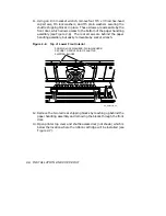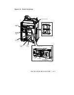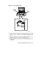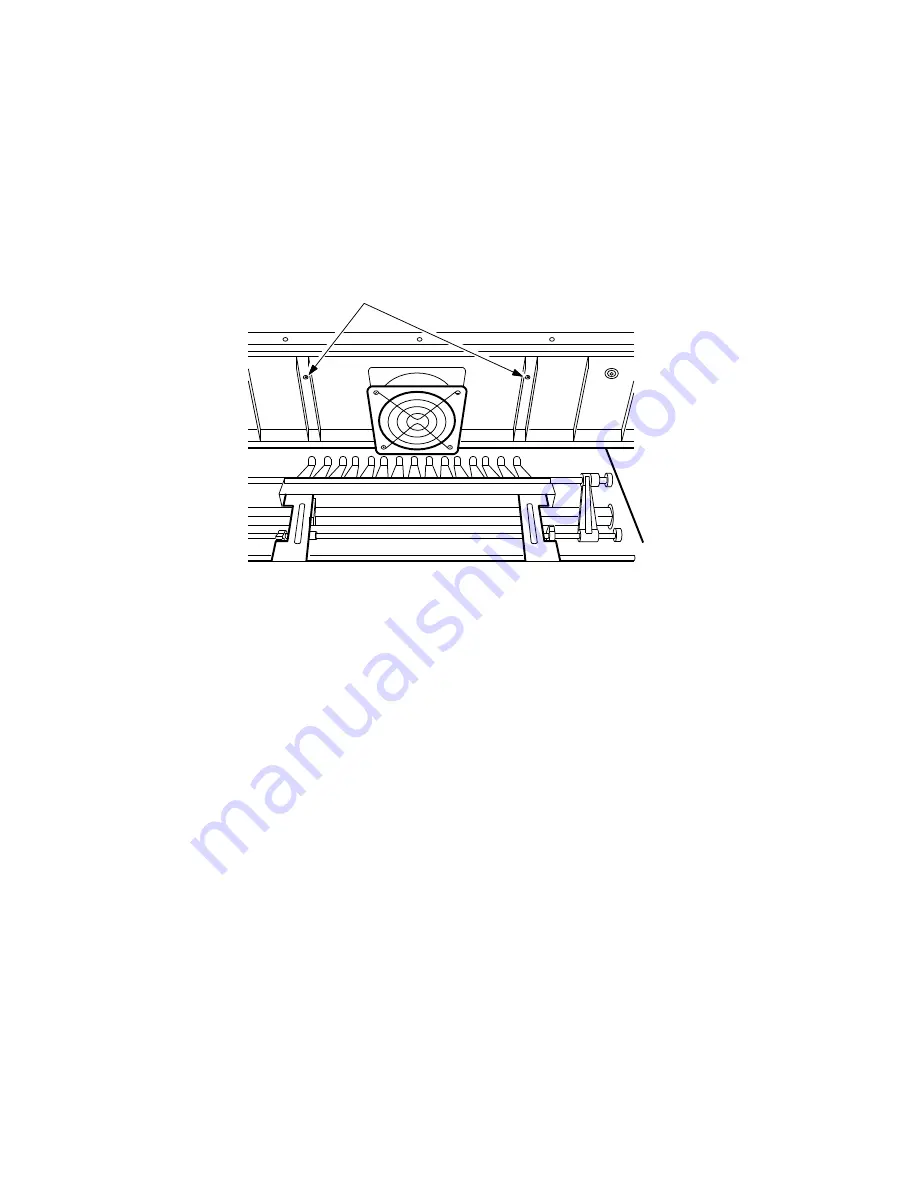
11. Using an 8 mm socket wrench, remove four M5 x 30 red hex-head
cap screws, M5 lock washers, and M5 plain washers securing the
shuttle shipping blocks in place. These screws are accessible by the
front door, which allows access to the bottom of the paper handling
assembly (see Figure 2–6). The rear screws are behind the paper
handling assembly, but easily removable by socket wrench.
Figure 2–6:
Top of Lower Front Interior
SCREWS, LOCKWASHERS, PLAIN WASHERS
SECURE TO FRONT PAIR OF SHUTTLE
SHIPPING BLOCKS
RE_UK00307A_89
12. Remove the two red rear shipping blocks by reaching up behind the
paper handling assembly and removing the blocks through the front
door.
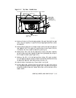
13. Open printer top cover and shuttle access door (not shown) which is
below the location where the ribbon cartridge will be installed (see
Figure 2–7).
2–8
INSTALLATION AND CHECKOUT


