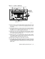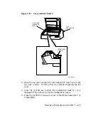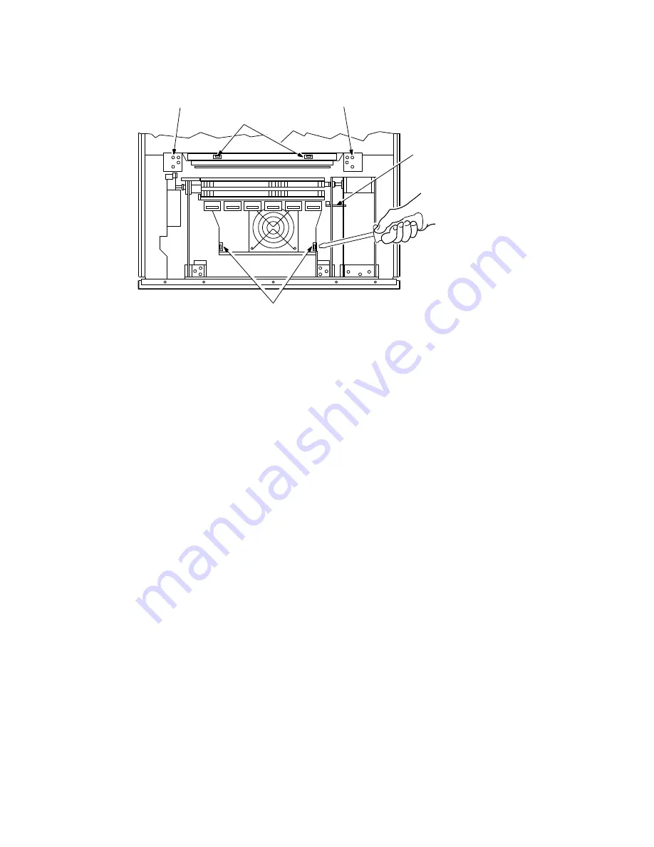
Figure 2–7:
Top View - Shuttle Area
RE_UK00752A_89
RED SHUTTLE SHIPPING BLOCKS
(REAR PAIR)
RED SHUTTLE SHIPPING BLOCKS
(FRONT PAIR)
SCREW (RED),
LOCKWASHER,
PLAIN WASHER,
& SHIPPING BRKT.
SECURING SHUTTLE
M5 CAP SCREWS (RED) SECURING STRIKER BAR SUPPORT DURING SHIPPING
14. Remove the two red front shipping blocks through the shuttle access
door. Use a screwdriver to pry the front shipping blocks from under
the shuttle.
15. Remove the sample print out sheet. Retain for future test comparison
(see Section 2.5). It is useful to move tractors to give more room for
instruction 16. Care must be taken to avoid injury.
16. Remove two M5 x 28 red hex-head cap screws and plain washers
securing the striker bar support blocks during shipping by using an
8 mm socket wrench (see Figure 2–7).
17. Remove the M5 x 16 red hex-head cap screw, M5 plain washer,
turn shipping bracket used as shuttle horizontal constraint during
shipping through 90° and slide out (see Figure 2–7).
18. Adjust printer leveling feet, if the printer is not level.
19. Install paper rack on back of printer as shown in Figure 2–8. Secure
four grounding cables to stubs on paper rack. The other end of each
grounding cable is secured inside the printer at the corners of the
paper chute.
INSTALLATION AND CHECKOUT
2–9


