background image

7.3 Dot Matrix Display

The indicators (Section 7.2) and the dot matrix display support the same four
languages. The dot matrix display shows three types of messages: activity,
status, and error.

7.3.1 Activity Messages

The dot matrix display has several activity messages: READ when the drive
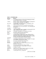
is reading, REWIND when it is rewinding, and so forth. Table 7–2 lists the
possible display messages.

7.3.2 Status Messages

The dot matrix display shows the current status of the autoloader when the
drive is not active. Table 7–2 lists the possible display messages.

7.3.3 Error Messages

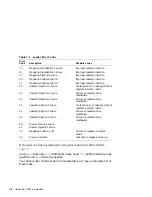
If an error occurs while the unit is operating, an error code will be displayed
on the dot matrix display.

If the error is with the loader mechanism the dot matrix panel will display:

ERROR xx

Where

xx

is a two digit error code. Use Table 7–1 to determine the meaning of

the code.

Using the TLZ7L autoloader 7–5

Summary of Contents for TLZ07

Page 1: ...TLZ07 Cassette Tape Drive and Autoloader Owner s Manual Order Number EK TLZ07 OM B01 Digital Equipment Corporation ...

Page 2: ...ound to comply with the limits for a Class B computing device in accordance with the specifications in Subpart J of Part 15 of FCC Rules which are designed to provide reasonable protection against such interference in a residential installation However there is no guarantee that interference will not occur in a particular installation If this equipment does cause interference to radio or televisio...

Page 3: ...ndesamt für Zulassungen in der Telekommunikation BZT das Inverkehrbringen dieses Gerätes angezeigt und die Berechtigung zur Überprüfung der Serie auf Einhaltung der Bestimmungen eingeräumt Betreiberhinweis Wir sind verpflichtet Sie auf folgende Fakten hinzuweisen BMPT Amtsblattverfügung 243 91 bzw 1046 84 2 Abschnitt 5 Dieses Gerät wurde funktechnisch sorgfältig entstört und geprüft Wird dieses Ge...

Page 4: ......

Page 5: ...ives Loaders TLZ07 TLZ7L 2 1 General 2 1 2 2 Shut Down Halt and Power Off the System 2 1 2 3 Selecting the SCSI Address 2 2 2 4 Connecting a SCSI Signal Cable Drive to System 2 3 2 5 Adding Another Tabletop Drive Drive to Drive 2 4 2 6 Connecting the Power Cable 2 4 3 Installing the TLZ07 AA BA Cassette Tape Drive 3 1 General 3 1 3 2 Shut Down Halt and Power Off the System 3 1 3 3 Selecting the SC...

Page 6: ...te Tape into the Drive 5 6 6 Preventive Maintenance and Problem Solving 6 1 Cleaning the Heads 6 1 6 2 Problem Solving 6 3 6 2 1 System Based Diagnostics 6 4 6 3 Repair Services 6 4 6 3 1 On Site Service 6 4 6 3 2 BASIC Service 6 4 6 3 3 DECservice 6 5 6 3 4 Carry In Service 6 5 6 3 5 DECmailer Service 6 5 6 3 6 Per Call Service 6 5 7 Using the TLZ7L autoloader 7 1 Overview 7 1 7 2 Indicators 7 1 ...

Page 7: ...TLZ07 Compression and Noncompression Modes B 1 B 2 OSF DUMP Utility B 1 B 3 OpenVMS TLZ07 Compression and Noncompression Modes B 2 Index Figures 1 1 Model TLZ07 DA Tabletop Original Version 1 4 1 2 Revised Version TLZ07 DA Tabletop Tape Drive 1 5 1 3 Model TLZ07 AA 3 5 inch Chassis and TLZ07 BA 5 25 inch Form Factor Original Version 1 6 1 4 Revised Version TLZ07 AA BA Tape Drive 1 7 3 1 SCSI Addre...

Page 8: ...2 Settings 7 10 7 5 SW2 Settings and Functions 7 11 7 6 SCSI ID Select Switch 7 12 7 7 SCSI ID Switch Settings on Switchpack 3 0 Off 1 On 7 12 A 1 TLZ07 Cassette Tape Drive Specifications A 1 A 2 TLZ07 Cassette Tape Drive Dimensions A 2 A 3 TLZ07 DA Noise Declaration A 3 A 4 TLZ7L Cassette Tape Drive Specifications A 4 A 5 TLZ7L Cassette Tape Drive Dimensions A 5 A 6 TLZ7L DA Noise Declaration A 5...

Page 9: ...Note 3 NOTE 1 The TLZ07 is compatible with 60 m cassette tapes written on the TLZ04 in the noncompressed mode only 2 The TLZ07 7L is compatible with the TLZ06 6L using 60 m and 90 m tapes only 3 The compression measurements are typical for a 2 to 1 data compression ratio but the actual ratio is dependent on the data The maximum time to back Up read or write on a TLZ07 cassette tape in a continual ...

Page 10: ... located on a rapidly rotating cylinder or drum that is tilted at an angle in relation to the vertical axis of the tape This causes the tracks to be recorded diagonally across the tape resulting in an extremely high recording density far higher than what is achievable with stationary head devices 1 2 2 What is Digital Data Storage DDS DDS uses a recording format that supports the use of digital au...

Page 11: ...nit with a built in power supply and fan Figure 1 1 and Figure 1 2 Model TLZ07 AA a 3 1 2 inch half height drive that mounts internally Figure 1 3 and Figure 1 4 Model TLZ07 BA a 3 1 2 inch drive in a 5 1 4 inch half height form factor allowing the drive to be mounted internally Figure 1 3 and Figure 1 4 Model TLZ07 VA a TLZ07 AA mounted in a 3 1 2 inch StorageWorks SBB Model TLZ7L AA a 5 1 4 inch...

Page 12: ...top Original Version Indicator PowerOn Indicator Indicator SCSIConnectors On OffSwitch SCSIIDSwitch PowerConnector TapeUnload Button WriteProtect Tape Activity FrontView RearView 5 0 1 4 TLZ07 Cassette Tape Drive Product Description ...

Page 13: ...top Tape Drive Front View Rear View Tape Unload Button SCSI Connectors SCSI ID Switch Power Connector Write Protect Indicator Tape Activity Indicator Power On Indicator On Off Switch 5 MA00456 TLZ07 Cassette Tape Drive Product Description 1 5 ...

Page 14: ...l Version SW1 RearView 50 2 JP4 U2 SW 321 PowerConnector SCSIIDand SCSIConnector TapeUnload Button TapeUnload Button TapeUnload Button TapeUnload Button TapeUnload Button TapeUnload Button WriteProtect Tape ActivityIndicator FrontView TerminatorResistor PackSockets PlacePin1here RemoteIDPins refertotextfor switchsettings OptionSwitch TermPower 1 6 TLZ07 Cassette Tape Drive Product Description ...

Page 15: ... BA Tape Drive SCSI Address Switch Power Connector Jumper Block Tape Unload Button Write Protect Tape Activity SCSI Connector Front View Rear View Bottom View MA00457 Indicator Indicator TLZ07 Cassette Tape Drive Product Description 1 7 ...

Page 16: ...nt includes the following One TLZ7L DA tabletop autoloader One 50 pin to 50 pin SCSI signal cable PN 17 01351 01 for drive to drive connections only AC power cable Five pack of blank cassette tapes 4 mm x 120 m PN TLZ07 CB One head cleaning cassette tape PN TLZ04 HA SCSI terminator PN 12 30552 01 Four slot tape cassette magazine PN TLZ06 04 1 3 3 Ordering Additional Cassettes To order additional b...

Page 17: ...ector Read the following sections to complete the installation 2 2 Shut Down Halt and Power Off the System If you are installing a TLZ07 DA tabletop cassette tape drive or TLZ7L DA tabletop autoloader on a running system have your system manager perform the following steps 1 Shut down the operating system 2 Halt the system 3 Set all system power switches off Installing the Tabletop Drives Loaders ...

Page 18: ...using SCSI ID 0 use any available SCSI ID You may have to consult your system manager To set change the SCSI address 1 Locate the SCSI address switch at the rear of the tabletop enclosure 2 Select the SCSI address for the drive TLZ07 DA Press the or button until the desired address 0 through 7 appears in the window See Figure 1 1 TLZ7L DA Set the switches according to Table 7 6 and Figure 7 4 NOTE...

Page 19: ...m you should use the SCSI signal cable supplied as part of your system installation kit If you do not have this cable contact your Digital sales representative You should use a cable supplied by Digital Equipment Corporation Failure to do so can result in degraded performance of your tabletop drive To connect a SCSI cable drive to system perform the following 1 Connect one end of the cable to the ...

Page 20: ... SCSI drive observing the correct orientation of the cable connector 3 Secure the SCSI cable by snapping the wire cable clamps on either side of the SCSI connector into place 4 Connect the other end of the SCSI signal cable to either SCSI connector on the TLZ07 DA drive or TLZ7L DA autoloader observing the correct orientation of the cable connector 5 Secure the SCSI cable by snapping the wire cabl...

Page 21: ... the power cable to a nearby ac outlet NOTE Multivendor Customer Services personnel The power cable disconnects the drive from the main ac power source Proceed to Chapter 4 Installing the Tabletop Drives Loaders TLZ07 TLZ7L 2 5 ...

Page 22: ......

Page 23: ...tem enclosure or external expansion box Read the following sections to complete the installation 3 2 Shut Down Halt and Power Off the System If you are installing a TLZ07 drive on a running system have your system manager perform the following steps 1 Shut down the operating system 2 Halt the system 3 Set all system power switches off Installing the TLZ07 AA BA Cassette Tape Drive 3 1 ...

Page 24: ...gure 3 2 for switch and jumper configuration 2 Select a unique address number with the first three switches on the right 3 To set a switch use a pen NOT A PENCIL to push the switch to the OFF or ON position Table 3 1 shows the SCSI IDs 0 through 7 and Figure 3 1 and Figure 3 2 show a close up view of the switches jumpers NOTE If you are installing the tabletop variant refer to Chapter 2 Turn off a...

Page 25: ...itchpack must be set to the factory default setting of all switches off ID 0 Table 3 1 SCSI ID Switch Settings 0 Off 1 On SCSI ID S3 S2 S1 0 0 0 0 default setting 1 0 0 1 2 0 1 0 3 0 1 1 4 1 0 0 5 1 0 1 6 1 1 0 7 1 1 1 Installing the TLZ07 AA BA Cassette Tape Drive 3 3 ...

Page 26: ...or new switch settings to take effect 1 2 3 4 5 6 7 8 Self Test Drive Mode Compression Parity Media Recognition System SCSI ID Default Settings MR 6417 AI NOTE Switch S7 allows the drive to report itself as an Archive Python for compatibility with industry standard PC software When the switch is in the OFF position the drive reports itself as a DEC TLZ07 ON position the drive reports itself as an ...

Page 27: ...ersion jumper JP4 located near the terminator was used to provide terminator power to the SCSI bus and to the terminator Termination was provided by installation of two single inline packages SIPs Remote SCSI ID jumpers were provided next to the SCSI connector 3 3 2 Revised Version TLZ07 AA BA Tape Drive SCSI Jumper Settings This subsection defines the revised version TLZ07 AA BA jumper settings R...

Page 28: ...LZ07 drive directly to your system you should use a SCSI signal cable supplied as part of your system installation kit If you do not have this cable contact your Digital sales representative You should use a cable supplied by Digital Failure to do so can result in degraded performance of your TLZ07 drive To connect a SCSI cable drive to system perform the following 1 Connect one end of the cable t...

Page 29: ...of the drive Figure 1 3 and Figure 1 4 NOTE Digital service personnel The power cable disconnects the drive from dc power generated by the main ac power source CAUTION Always use M3 screws with a maximum thread length of 5 mm to mount the TLZ7L autoloader Installing the TLZ07 AA BA Cassette Tape Drive 3 7 ...

Page 30: ......

Page 31: ...oximately 1 to 5 seconds and then extinguish With a cassette in the drive the Tape activity indicator will continue flashing approximately 20 seconds until the cassette is loaded 3 After successful completion of POST the Tape activity and Write Protect indicators turn off If a cassette is loaded the cassette LED will remain on 4 If the Write Protect indicator flashes amber and the drive indicator ...

Page 32: ...stem and assign a device name to your TLZ07 drive Optionally you can run a full system or SCSI bus test See your system owner s manual for specific instructions NOTE If a tape is loaded the Tape activity indicator stays on 4 2 Verifying TLZ07 Cassette Tape Drive Installation ...

Page 33: ...ime check with your system manager for the correct procedure to shut down your system or power off the drive 5 3 Unload Button Press and hold the unload button for 1 to 2 seconds to eject the cassette tape CAUTION Pressing the unload button during normal tape operations may halt the tape operation in progress 5 4 Write Protect LED This indicator comes on amber when the cassette is write protected ...

Page 34: ...e activity LEDs In the normal operating state the Write Protect LED is used to indicate write protect status only In the normal operating state the Tape activity LED is used to indicate drive activity and tape load status 5 2 Using the TLZ07 Cassette Tape Drive ...

Page 35: ...shes amber 2 Hz for duration of test Write protect status when self test completes Flashes green 2 Hz for duration of test Normal activity indications when self test complete Lvl 2 Extended self test Write protect status Flashes green until test complete 1 to 4 minutes Same as normal activity indication Test complete no failure Resume normal operation write protect status Test failure drive fault ...

Page 36: ... may result in degraded drive performance We recommend the use of Digital Equipment Corporation media 5 7 1 Proper Handling of Cassette Tapes To ensure optimal performance from your cassette tapes observe the following guidelines when handling them Avoid placing the cassette tapes near sources of electromagnetic interference such as terminals and video or X ray equipment Emissions from such equipm...

Page 37: ... 5 1 to the desired position NOTE The tab is not visible when the cassette tape is loaded in the TLZ07 drive Figure 5 1 TLZ07 Cassette Tape TAB PROTECTED ENABLED WRITE WRITE WRITE PROTECT Observe the following guidelines when setting the write protect tab If you are reading data copying from the tape set the write protect tab to write protected by sliding the tab to the left If you are writing dat...

Page 38: ...write protect tab on the right facing you Remove the tape by depressing the tape eject button CAUTION The drive should never be transported with a tape loaded in the drive Tape damage and possible loss of data may result Always unload the tape prior to transporting the drive 5 6 Using the TLZ07 Cassette Tape Drive ...

Page 39: ... of the drive 6 1 Cleaning the Heads This section shows you how to perform TLZ07 head cleaning The heads are the components that physically read and write data to and from the media in this case a cassette tape Digital Equipment Corporation recommends that you perform the head cleaning procedure after the first four hours of tape movement with a new cartridge and thereafter once every 2 weeks or a...

Page 40: ...er approximately 30 seconds if head cleaning is successful 4 On the card enclosed with the head cleaning cassette record every time you use the cassette Under normal conditions the head cleaning cassette is used for about 25 cleanings Additional cassettes are available from your Digital sales representative or DECdirect If the number of cleaning cycles of a particular head cleaning cassette has ex...

Page 41: ...Dirty heads or bad media Eject tape Perform head cleaning procedure see Section 6 1 If error repeats try another tape Drive error possibly a hard failure Eject tape Power off and power on the drive If error repeats call Multivendor Customer Services After applying power and self test has completed successfully the Tape activity LED is not lit No tape loaded Load tape Unit not available to system D...

Page 42: ...ics are subject to software licensing Consult your Digital sales representative 6 3 Repair Services Multivendor Customer Services offers a range of flexible service plans 6 3 1 On Site Service On site service offers the convenience of service at your site and insurance against unplanned repair bills For a monthly fee you receive personal service from our service specialists Within a few hours the ...

Page 43: ...onnel repair your unit within 2 days This service is available on selected terminals and systems Contact your local unit Digital SERVICenters are open during normal business hours Monday through Friday 6 3 5 DECmailer Service DECmailer offers expert repair at a per use charge This service is designed for users who have the technical resources to troubleshoot identify and isolate the module causing...

Page 44: ......

Page 45: ...f storage 7 2 Indicators The TLZ7L autoloader has four LED indicators The labels for these LED indicators come with the autoloader They are provided in four languages English French German and Spanish and two orientations vertical and horizontal Choose your labels and place them on the bezel as shown in Figure 7 1 Note that in the vertical orientation the left side of the loader will be on the bot...

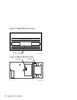
Page 46: ...Model TLZ7L AA Front View Write Protect Eject Cassette DC Slot Select Dot Matrix Display LJ 03001 TI0 DDS 2 Figure 7 2 Model TLZ7L AA Top View Switchpack 1 Switchpack 2 LJ 03002 TI0 7 2 Using the TLZ7L autoloader ...

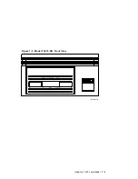
Page 47: ...Figure 7 3 Model TLZ7L DA Front View Write Protect Eject Cassette DC Slot Select LJ 03387 TI0 DDS 2 Using the TLZ7L autoloader 7 3 ...

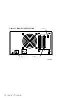
Page 48: ...Figure 7 4 Model TLZ7L DA Back View ID Select On Off Switch SCSI Connector LJ 03386 TI0 7 4 Using the TLZ7L autoloader ...

Page 49: ... Table 7 2 lists the possible display messages 7 3 2 Status Messages The dot matrix display shows the current status of the autoloader when the drive is not active Table 7 2 lists the possible display messages 7 3 3 Error Messages If an error occurs while the unit is operating an error code will be displayed on the dot matrix display If the error is with the loader mechanism the dot matrix panel w...

Page 50: ...tion Failure Failure of cassette drive mechanism 50 Cassette Ejection Failure Contamination or misalignment of cassette insertion rollers 51 Cassette Ejection Failure Failure of cassette drive mechanism 52 Cassette Ejection Failure Failure of cassette drive mechanism 60 Drawer Closing Failure 61 Drawer Opening Failure 70 Magazine Position Lost Failure of magazine position sensor F0 Power up Failur...

Page 51: ... being ejected to slot n EJECT A cartridge cannot be ejected due to a tape in the slot of the magazine at present position Depress the eject button to unload the magazine Depress the eject button again to unload the tape in the drive Remove the tape and reload the magazine EJECTING The magazine is being ejected to the dismount position EMPTY This message is displayed when there is no magazine in t...

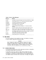
Page 52: ...ly inserted cartridge is being written WRITE n The cartridge from slot n is being read 7 4 Operation The TLZ7L autoloader can be operated two ways automatically or manually It has two modes Sequential and Random Access CAUTION Never transport the loader with a magazine installed in the loader Damage to the tape loader or magazine may result due to magazine movement Data loss may occur if a tape is...

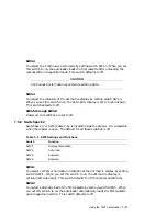
Page 53: ...earance below the loader or beside the loader if vertically mounted to allow the magazine to move freely to all available slots To load a cassette press the slot button Press it once to load the first cassette twice to load the second cassette and so on If you make a mistake continue pressing the slot button until the desired slot number is shown on the dot matrix display When you press the slot b...

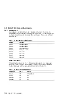
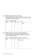
Page 54: ...h Function SW1 1 Language Select SW1 2 Language Select SW1 3 Continuous Cycle SW1 4 Display Intensity SW1 5 Reserved SW1 6 Reserved SW1 7 Reserved SW1 8 Reserved SW1 1 and SW1 2 The dot matrix display on the TLZ7L autoloader supports four languages English French German and Spanish You select the language of the dot matrix display by setting switches SW1 1 and SW1 2 Table 7 4 Table 7 4 SW1 1 and S...

Page 55: ...itchpack 2 or SW2 Table 7 5 is located inside the drawer It is accessible when the drawer is open The default for all these switches is off Table 7 5 SW2 Settings and Functions Switch Function SW2 1 Display Orientation SW2 2 Auto load SW2 3 Reserved SW2 4 Reserved SW2 1 You select vertical or horizontal orientation of the dot matrix display by setting switch SW2 1 When you set this switch to on th...

Page 56: ...0 Default 1 0 0 0 1 2 0 0 1 0 3 0 0 1 1 4 0 1 0 0 5 0 1 0 1 6 0 1 1 0 7 0 1 1 1 7 5 4 SCSI ID Select Switch AA Version Only Switchpack 3 The SCSI ID switches comprise S1 S3 on switchpack 3 at the rear of the internal autoloader Figure 7 5 Table 7 7 indicates the proper switch positions for each possible SCSI ID Table 7 7 SCSI ID Switch Settings on Switchpack 3 0 Off 1 On SCSI ID S3 S2 S1 0 0 0 0 f...

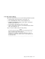
Page 57: ...Drive Mode S7 Switch defaults to off for TLZ07 mode Power on self test POST diagnostic mode enable disable S8 Default POST mode enabled S8 on Figure 7 5 shows the default settings for these switches NOTE The drive must be turned off and then on for switch settings to take effect or a SCSI bus reset must be received Although S6 is the default on compression disabled you may turn compression on and ...

Page 58: ... report itself as an Archive Python for compatibility with industry standard PC software When the switch is in the OFF position the drive reports itself as a DEC TLZ07 ON position the drive reports itself as an Archive Python 7 5 6 Termination Jumper Terminators The last unit in a daisy chain of SCSI devices must have termination installed For the internal unit two single inline packages SIPs prov...

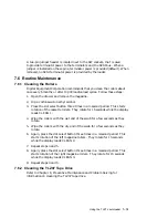
Page 59: ...tation of the cassette rollers They rotate for 15 seconds while the display reads CLEAN 1 4 Wipe the rollers with the wet end of the swab for a few seconds as they rotate 5 Wipe the rollers with the dry end of the swab for a few seconds as they rotate 6 Again press the slot select button three times in a 3 second period This starts rotation of the left magazine rollers They rotate for 15 seconds w...

Page 60: ......

Page 61: ...e tape Bit density 114 Mbits per square inch Transfer rate typical 400 Kbyte s noncompression Recording format Digital data storage DDS 2 DDS DC Cassette capacity typical 4 gigabytes with 120 meter tape in native mode 8 gigabytes typical with 120 meter tape and data compression Operating temperature 10 C to 40 C 50 F to 104 F Nonoperating temperature 40 C to 70 C 40 F to 158 F Operating humidity 2...

Page 62: ...nts Tabletop TLZ07 DA 100 to 240 V ac 0 3 A Drive TLZ07 AA BA 5 V dc 0 89 A Drive TLZ07 AA BA 12 V dc 0 2 A Table A 2 TLZ07 Cassette Tape Drive Dimensions Dimensions TLZ07 AA TLZ07 BA TLZ07 DA Height 41 2 mm 1 6 in 41 2 mm 1 6 in 85 mm 3 4 in Width 101 6 mm 4 0 in 146 mm 5 7 in 135 mm 5 3 in Length 146 mm 5 7 in 175 mm 6 9 in 235 mm 9 3 in Weight 85 kg 2 lb 1 1 kg 2 4 lb 2 4 kg 5 2 lb A 2 Cassette...

Page 63: ...e Werteangaben nach ISO 9296 und ISO 7779 DIN EN27779 LwAd LpAm Zuschauerpositionen Leerlauf 4 7 B 34 dBA Betrieb 4 8 B 35 dBA NOTE Current values for specific configurations are available from Digital representatives 1 B 10 dBA Aktuelle Werte für spezielle Ausrüstungsstufen sind über die Digital Equipment Vertretungen erhältlich 1 B 10 dBA Cassette Tape Drive Specifications A 3 ...

Page 64: ...n Magazine capacity 12 cartridge typical 64 gigabytes 96 gigabytes typical with data compression Operating temperature Table A 1 applies Nonoperating temperature Table A 1 applies Operating altitude Table A 1 applies Nonoperating altitude Table A 1 applies Passes per cassette tape Table A 1 applies Power consumption TLZ7L AA Typical 28 9 W Power consumption TLZ7L DA Typical 19 W Maximum 22 W Power...

Page 65: ...96 and ISO 7779 LwAd LpAm bystander positions Idle 6 0 B 44 dBA Operating 6 2 B 46 dBA Schallemissionswerte Werteangaben nach ISO 9296 und ISO 7779 DIN EN27779 LwAd LpAm Zuschauerpositionen Leerlauf 6 0 B 44 dBA Betrieb 6 2 B 46 dBA NOTE Current values for specific configurations are available from Digital representatives 1 B 10 dBA Aktuelle Werte für spezielle Ausrüstungsstufen sind über die Digi...

Page 66: ......

Page 67: ...ers that should be used when running the DUMP utility on a TLZ07 tape drive in compressed and noncompressed mode are as follows Noncompressed Mode density 61000 effective tape length with 120 meter tape size 76586 with 120 meter tape Example dump 0dsf 61000 76586 dev rmt 1 dev rrz0g Compressed Mode density 61000 effective tape length with 120 meter tape size 76586 with 120 meter tape 2 compression...

Page 68: ...TLZ07 tape drive in noncompression mode specify MEDIA_FORMAT NOCOMPACT software switch Examples for enabling disabling compression are INIT MEDIA_FORMAT NO COMPACT MKx MOUNT MEDIA_FORMAT NO COMPACT MKx BACKUP MEDIA_FORMAT NO COMPACT MKx NOTE To be sure that the compression is enabled disabled you should include the correct software switch with each command line B 2 Enabling Disabling Data Compress...

Page 69: ...es 6 4 dot matrix display 7 5 Drive indicator 5 2 E Enabling Disabling Data Compression B 1 error messages 7 5 H Head cleaning 6 1 Head cleaning cassette 6 2 I indicators TLZ7L autoloader 7 1 Inserting a cassette tape into the drive 5 6 Installing the TLZ07 AA BA cassette tape drive 3 1 M Media Recognition System MRS 1 3 messages activity 7 5 error 7 5 status 7 5 O Ordering additional cassettes 1 ...

Page 70: ...tape drive indicators 5 5 installation verification 4 1 location of buttons switches connectors 3 2 location of buttons switches connectors 2 2 power button 5 1 specifications A 1 unload button 5 1 using 5 1 write protect LED 5 1 TLZ7L autoloader indicators 7 1 TLZ7L cassette tape drive specifications A 1 TLZ7L cassette tape loader location of buttons switches connectors 2 2 U Unload button 5 1 W ...

Reviews: