background image

Removing and Replacing FRUs

3–7

3.

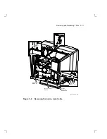
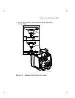
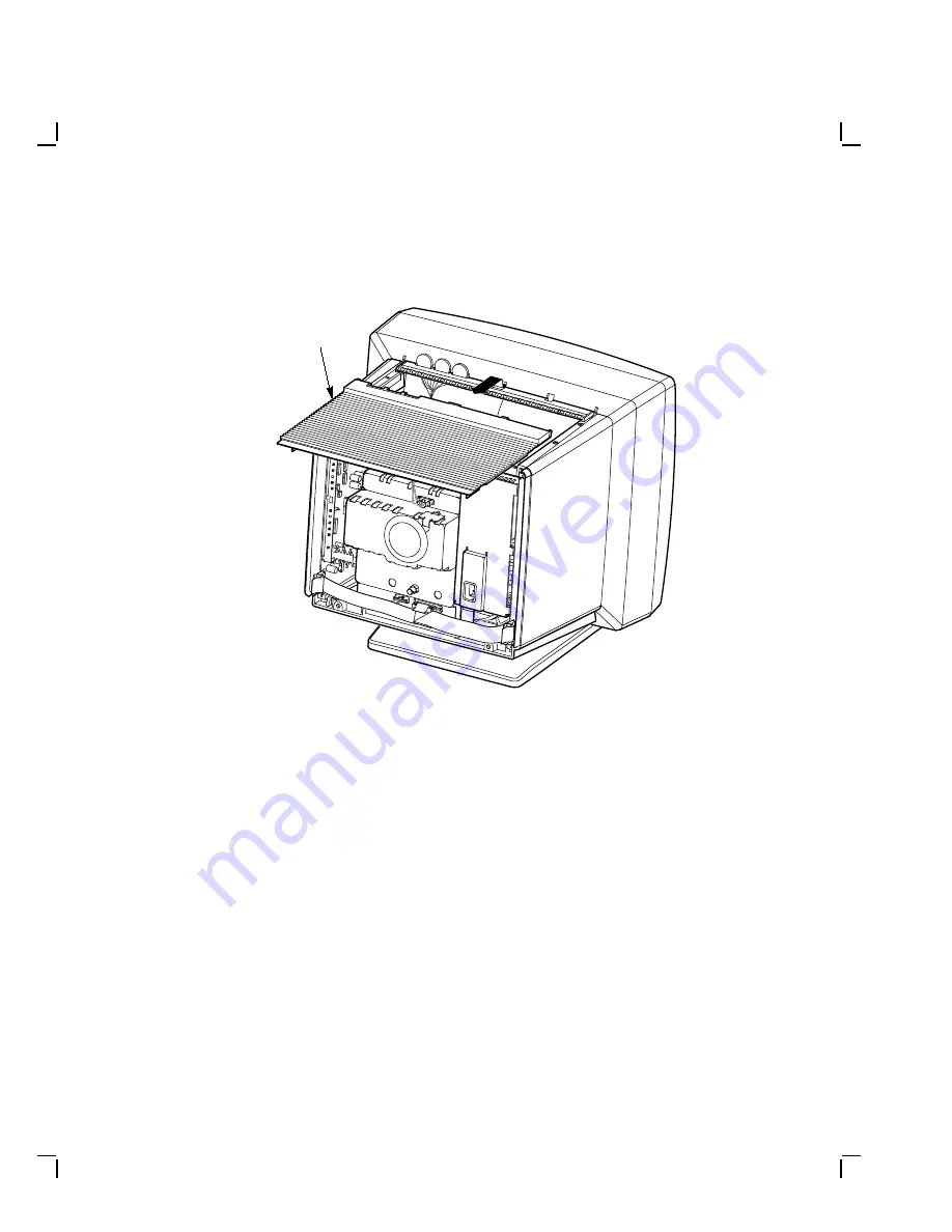
Slide the top cover toward the back of the monitor (Figure 3–6).

M A - 1 2 2 6 - 8 9 . D G

T o p
C o v e r

Figure 3–6

Removing the Top Cover

Summary of Contents for VR319

Page 1: ...VR319 Monitor Service Guide Order Number EK VR319 SV 001 Digital Equipment Corporation ...

Page 2: ...is not supplied by Digital Equipment Corporation or its affiliated companies Restricted Rights Use duplication or disclosure by the U S Government is subject to restrictions as set forth in subparagraph c 1 ii of the Rights in Technical Data and Computer Software clause at DFARS 252 227 7013 Copyright Digital Equipment Corporation 1990 All Rights Reserved Printed in U S A The following are tradema...

Page 3: ...eshooting Procedures 2 2 2 3 Troubleshooting Tables 2 2 3 Removing and Replacing FRUs 3 1 Procedures 3 1 3 1 1 Rear Cover Removal 3 2 3 1 2 Top Cover Removal 3 6 3 2 Field Replaceable Units FRUs 3 8 3 2 1 Interconnect Cable 3 9 3 2 2 Deflection Module 3 10 3 2 3 Video Casting Assembly 3 15 3 2 4 CRT Discharge 3 19 3 2 5 Power Supply Module 3 21 3 2 6 CRT Chassis Assembly 3 25 3 3 CRT Disposal Trai...

Page 4: ... HPHASE HLIN HCEN 4 9 4 4 2 Horizontal Width WIDTH 4 12 4 5 Vertical Hold Adjustment VHOLD 4 13 4 6 Bias Adjustment G2 4 15 4 7 Using the Radiance Meter 4 16 4 8 Gain Adjustment GGAIN 4 18 4 9 Focus Adjustments G4 4 19 4 9 1 Vertical Dynamic Focus VPARAB 4 21 4 9 2 Horizontal Dynamic Focus HPARAB 4 21 5 Changing the Refresh Rate 5 1 VR319 Monitor Refresh Rates 5 1 5 2 Changing the Refresh Rate 5 1...

Page 5: ...n Deflection Module 3 14 3 13 Disconnecting the Interconnect Cable 3 15 3 14 Disconnecting the Brightness Contrast Cable 3 16 3 15 Removing the CRT Socket Connector 3 17 3 16 Removing the Video Casting 3 18 3 17 Discharging the CRT and Removing the Anode Cap 3 20 3 18 Disconnecting the Interconnect Cable 3 21 3 19 Removing the LED Cable from the Power Supply 3 22 3 20 Removing the Power Supply 3 2...

Page 6: ...ch Pattern 4 19 4 16 Focus Control G4 4 20 5 1 Product Conversion Label 5 3 A 1 Circle Crosshatch Pattern A 1 A 2 All White Pattern A 2 Tables 1 1 Refresh Rates of Monitor Models 1 2 1 2 Tools and Equipment 1 2 1 3 VR319 Recommended Spares 1 3 2 1 Blank Screen No Video or Raster 2 3 2 2 Blank Screen No Video but Raster Present 2 4 2 3 Poor Display Quality 2 5 5 1 Monitor Model Refresh Rates 5 1 5 ...

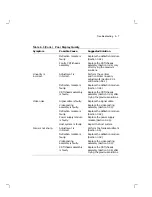
Page 7: ...e Units FRUs Chapter 4 describes the alignment procedures Chapter 5 describes the procedures to change the refresh rate of the monitor Appendix A describes the alignment screens Appendix B describes related documentation Audience The procedures in this manual are for service technicians trained only by Digital Equipment Corporation Conventions Warning Provides information to prevent personal injur...

Page 8: ...s a direct viewed 500 mm antiglare CRT The built in tilt swivel assembly lets the user adjust the screen for viewing comfort When connected to a host system the monitor can display information that the host system sends to it MA 0243 90 DG Figure 1 1 VR319 Monochrome Monitor 1 1 ...

Page 9: ... rates Table 1 1 Refresh Rates of Monitor Models Model Pixels x Lines Refresh Rate Applicable Area VR319 CA 1280 x 1024 66 Hz Northern Hemisphere VR319 C4 1280 x 1024 66 Hz Southern Hemisphere VR319 DA 1280 x 1024 72 Hz Northern Hemisphere VR319 D4 1280 x 1024 72 Hz Southern Hemisphere 1 2 Tools and Equipment You need the following tools and equipment to service the VR319 monitor Table 1 2 Tools a...

Page 10: ... monitor Table 1 3 VR319 Recommended Spares Spares Part Number Power supply module 54 19703 00 Deflection module 54 19303 01 Video casting assembly 70 27010 02 Interconnect cable 70 27000 01 CRT Chassis assembly Northern Hemisphere 70 27429 07 CRT Chassis assembly Southern Hemisphere 70 27429 08 ...

Page 11: ...f problem tell the customer to let the monitor warm up for at least 20 minutes if possible before you arrive and begin the troubleshooting procedures Magnetic fields affect monitor performance and can give a false indication of a monitor failure Place the monitor away from any electromagnetic devices such as printers and terminals or away from large magnetized objects such as filing cabinets and s...

Page 12: ...the suggested solutions 4 Display the host system alignment test patterns to make sure that no other problem exists Refer to the host system service guide for displaying test patterns 2 3 Troubleshooting Tables The troubleshooting tables list possible causes in order of probability This troubleshooting information applies to three types of video problems that the VR319 monitor may exhibit A blank ...

Page 13: ...ection module is faulty Replace the deflection module Section 3 2 2 Both the power indicator LED and the deflection module LED are on Contrast or brightness is set too low Adjust the contrast and brightness controls Internal cabling is loose or faulty Check all cabling going to the deflection module and the video casting assembly If necessary secure the cables G2 Bias is set too low Adjust the G2 ...

Page 14: ...ost system on Connect the signal cable to the monitor and host Internal cabling is loose or faulty Check all cabling to the deflection module and the video casting assembly The host system is not supplying video signals to the monitor Connect the monitor to a known working host system if available to verify the problem before replacing any monitor module or cable Video casting assembly is faulty R...

Page 15: ...ontal center adjustment Section 4 4 1 Perform the horizontal phase adjustment Section 4 4 1 Perform the vertical center adjustment Section 4 4 1 Deflection module is faulty Replace the deflection module Section 3 2 2 Display is too short Adjustment is incorrect Perform the height adjustment Section 4 3 2 Deflection module is faulty Replace the deflection module Section 3 2 2 Display is too tall Ad...

Page 16: ... 4 6 and GAIN adjustment Section 4 8 Video casting assembly is faulty Replace the video casting assembly Section 3 2 3 Deflection module is faulty Replace the deflection module Section 3 2 2 CRT wearout Replace the CRT chassis assembly Section 3 2 6 only after trying the previous solutions Display is too bright Brightness control is set to high Adjust the brightness control to the optimum range G2...

Page 17: ...is assembly Section 3 2 6 after trying the previous solutions Video noise Signal cable is faulty Replace the signal cable Video casting assembly is faulty Replace the video casting assembly Section 3 2 3 Deflection module is faulty Replace the deflection module Section 3 2 2 Power supply module is faulty Replace the power supply module Section 3 2 5 Host system is faulty Repair the host system Foc...

Page 18: ...om the rear of the monitor Tilt the monitor from the back to the front to allow easier access to the modules NOTE If you twist the monitor while applying the tilt pressure the monitor moves easily The procedures only describe how to remove FRUs to install each FRU reverse the removal procedure Before removing any FRUs you must remove the rear cover and the top cover NOTE Any time you replace a vid...

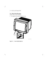
Page 19: ... 2 Removing and Replacing FRUs 3 1 1 Rear Cover Removal Remove the rear cover as follows 1 Turn power to the monitor off Figure 3 1 MA 1239 89 DG Power Switch Indicator Figure 3 1 Power Switch Indicator ...

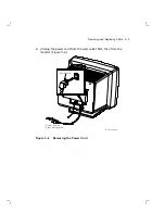
Page 20: ...ing and Replacing FRUs 3 3 2 Unplug the power cord from the wall outlet first then from the monitor Figure 3 2 M A 1 2 2 3 8 9 D G Power Cord Power Source From Host System Figure 3 2 Removing the Power Cord ...

Page 21: ... FRUs 3 Remove the signal cable from the rear of the monitor Push the connector in and turn it left until the signal cable is released from the connector Figure 3 3 M A 1 2 2 4 8 9 D G Signal Cable Figure 3 3 Sample Signal Cable ...

Page 22: ...our captive screws that hold the rear cover to the enclosure Figure 3 4 NOTE The rear cover may be difficult to pull off 5 Remove the rear cover by pulling the cover towards you M A 1 2 2 5 8 9 D G Allen Head Screw 4 Allen Driver Rear Cover Figure 3 4 Removing the Rear Cover ...

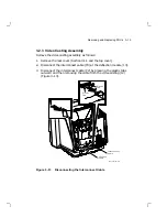
Page 23: ...ving and Replacing FRUs 3 1 2 Top Cover Removal Remove the top cover as follows 1 Remove the rear cover Section 3 1 1 2 Tilt the top cover up Figure 3 5 MA 1227 89 DG Top Cover Figure 3 5 Tilting the Top Cover ...

Page 24: ...Removing and Replacing FRUs 3 7 3 Slide the top cover toward the back of the monitor Figure 3 6 MA 1226 89 DG Top Cover Figure 3 6 Removing the Top Cover ...

Page 25: ... 7 Before replacing any FRUs see Section 3 1 WARNING Turn power to the monitor off and disconnect the power cord before disconnecting or replacing any FRU MA 1222 89 DG Video Casting Assembly Power Supply Interconnect Cable Deflection Module CRT Chassis Assembly Module Figure 3 7 VR319 Field Replaceable Units ...

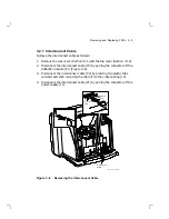
Page 26: ... cable P3 by pulling the connector off the deflection module J3 Figure 3 8 3 Disconnect the interconnect cable P2 by pressing the plastic tabs outward and then removing the cable from the video casting J2 4 Disconnect the interconnect cable P1 by pulling the connector off the power supply J1 M A 1 2 4 5 8 9 D G Interconnect Cable Plastic Tab Plastic Tab Figure 3 8 Removing the Interconnect Cable ...

Page 27: ...tion module 1 Remove the rear cover Section 3 1 1 2 Remove the top cover Section 3 1 2 3 Disconnect the interconnect cable P3 by pulling the connector off the deflection module J3 4 Disconnect the 2 wire 3 pin cable P7 on the video casting assembly by pressing the tabs on the connector J7 Figure 3 9 5 Remove the 2 wire 3 pin cable from the cable clamp on the video casting ...

Page 28: ...Removing and Replacing FRUs 3 11 M A 1 2 2 8 8 9 D G Video Casting Assembly Interconnect Cable Deflection Module 2 Wire 3 Pin Cable Cable Clamp Figure 3 9 Removing the 2 wire 3 pin Cable ...

Page 29: ... tabs on the connector J11 Figure 3 10 7 Disconnect the 9 wire 9 pin raster control cable P6 on the deflection module by pressing the tab on top of the connector J6 1 2 1 2 M A 1 2 2 9 8 9 D G Deflection Module 6 Wire 9 Pin CRT Yoke Cable 9 Wire 9 Pin Raster Control Cable Figure 3 10 Disconnecting Cables from the Deflection Module ...

Page 30: ...Removing and Replacing FRUs 3 13 8 Slide the deflection module out of the card guides Figure 3 11 M A 1 2 3 1 8 9 D G Card Guide Deflection Module Card Guide Figure 3 11 Removing the Deflection Module ...

Page 31: ...efresh rate setting on the module you are replacing and move the jumper if needed Refresh Rate Install Jumper On 66 Hz Left two pins 1 and 2 72 Hz Right two pins 2 and 3 If you need to change the refresh rate also check the setting of the power supply refresh jumper Figure 3 21 1 M A 1 2 3 0 8 9 D G 1 Deflection Module 66 72 Hz Deflection Jumper 72 Hz 66 Hz Figure 3 12 Refresh Rate Jumper on Defle...

Page 32: ...d the top cover 2 Disconnect the interconnect cable P3 at the deflection module J3 3 Disconnect the interconnect cable P2 by pressing the plastic tabs outward and then removing the cable from the video casting J2 Figure 3 13 MA 1232 89 DG Plastic Tab Deflection Module Interconnect Cable Plastic Tab Figure 3 13 Disconnecting the Interconnect Cable ...

Page 33: ...e connector next to the cable clamp so it does not interfere with the video casting removal procedure 6 Disconnect the 6 wire 8 pin brightness contrast cable P5 by pressing the tab on top of the connector J5 Figure 3 14 MA 1233 89 DG 2 Wire 3 Pin Cable 6 Wire 8 Pin Brightness Contrast Cable Figure 3 14 Disconnecting the Brightness Contrast Cable ...

Page 34: ...Removing and Replacing FRUs 3 17 7 Gently push the CRT socket connector off the socket pins Figure 3 15 MA 1235 89 DG Socket Pins CRT Socket Connector Figure 3 15 Removing the CRT Socket Connector ...

Page 35: ... the video casting assembly towards you 10 Gently lift the video enclosure assembly up and out of the chassis Figure 3 16 CAUTION When you install the video casting assembly carefully push the CRT socket connector onto the CRT neck Use care not to bend the pins during this procedure M A 1 2 3 7 8 9 D G Spring loaded Captive Screw 2 Video Casting Assembly Figure 3 16 Removing the Video Casting ...

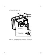
Page 36: ...or the video casting assembly Do not put the clip on the painted surface of the monitor WARNING Keep your free hand away from any part of the monitor during the anode discharge process 3 Using one hand carefully slip the anode discharge tool under the CRT anode connector cup until it touches the connector prongs Maintain contact for at least 10 seconds NOTE Be careful when you use the anode discha...

Page 37: ...ing FRUs A Push in the direction of the arrow B When one barb is free push in the opposite direction see arrows to remove anode cap MA 1238 89 DG Anode Discharge Tool Figure 3 17 Discharging the CRT and Removing the Anode Cap ...

Page 38: ... voltages from the CRT Section 3 2 4 before removing the power supply module 1 Remove the rear cover Section 3 1 1 2 Remove the top cover Section 3 1 2 3 Disconnect the interconnect cable from the power supply Figure 3 18 M A 1 2 4 0 8 9 D G Interconnect Cable Power Supply Module Figure 3 18 Disconnecting the Interconnect Cable ...

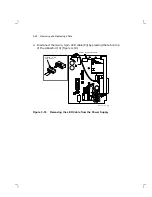
Page 39: ...FRUs 4 Disconnect the 3 wire 5 pin LED cable P4 by pressing the tab on top of the connector J4 Figure 3 19 1 M A 1 2 4 1 8 9 D G 1 3 Wire 5 Pin LED Cable Power Supply Module Figure 3 19 Removing the LED Cable from the Power Supply ...

Page 40: ...Us 3 23 5 Loosen the two captive screws on the power supply 6 Slide the power supply module out of the card guides Figure 3 20 M A 1 2 4 2 8 9 D G Phillips Head Screws 2 Power Supply Module Figure 3 20 Removing the Power Supply ...

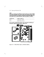
Page 41: ...r system The jumper covers all but one pin Refresh Rate Move Jumper To Cover 66 Hz Bottom pins top pin is free 72 Hz Top pins bottom pin is free If you change the refresh rate also check the setting of the deflection module jumper Figure 3 12 1 1 M A 1 2 4 3 8 9 D G 66 72 Hz Power Supply Jumper Power Supply Module 72 Hz 66 Hz Figure 3 21 Refresh Rate Jumper on the Power Supply ...

Page 42: ...r pressure outside the tube is greater than air pressure inside there is always the possibility of accidental implosion WARNING You must handle CRTs very carefully to avoid accidental implosion and shattering glass Use the following guidelines and disposal procedure to remove and dispose of a CRT These guidelines and procedure are Digital policy for all CRTs more than 7 6 cm 3 in in diameter NOTE ...

Page 43: ...sed container or mounted in the device cabinetry CRT Disposal Use the following procedure to safely dispose of CRTs Always perform this procedure at a Digital facility WARNING Do not dispose of any CRT until it is rendered inoperative and safe to dispose Never perform the following disposal procedure at the customer site Return the defective CRT to the local Digital facility for disposal At the Di...

Page 44: ... the container from which you removed the new CRT chassis assembly 2 Using pliers slowly crush but do not snap the evacuation point Figure 3 22 Do not move or disturb the CRT until the hissing sound of in rushing air has stopped CAUTION Use care not to break the unprotected glass area of the CRT neck that surrounds the evacuation point NOTE The evacuation point is a protrusion that extends from th...

Page 45: ...ure 3 22 CRT Disposal Procedure 3 Seal the carton with packing tape and dispose of it in the Digital site s trash receptacle NOTE The safe gassing of the CRT is necessary to prevent liability and safety problems that may arise from accidental CRT implosion ...

Page 46: ...e host system documentation to set up test patterns Use a metric measuring tape PN 29 25342 00 to measure the dimensions of the screen display To avoid scratching the screen with the tape s metal clip start the measurement at 10 cm Use a video alignment tool to make all adjustments except when noted Make sure all adjustments are made under these conditions 4 1 1 Before You Start NOTE If a customer...

Page 47: ...play on the screen 7 Verify that the user controls on the top of the monitor are in the center position of the thumbwheels 8 Slide the deflection module out one half inch to read the labels for the adjustment potentiometers 9 Rotate the monitor so the adjustments are on the right and the screen to view the test pattern is on the left 4 1 2 Displaying Screen Tests The procedures in this chapter ref...

Page 48: ...re performing any adjustments The warm up time ensures that the electron gun is at a stable temperature before you do any adjustments The user adjustments are shown in Figure 4 1 MA 1246 89 DG Rotation Horizontal Centering Vertical Centering Power Switch Indicator Contrast Brightness Figure 4 1 User Controls ...

Page 49: ...ts are set at the factory Therefore adjustment procedures for these controls are not included in this guide Slide the deflection module out one half inch to read the labels for the adjustment potentiometers Figure 4 2 MA 1247 89 DG Width HCen G2 G4 VCen VHold HHold Height VLin HLin GGain HPhase HParab VParab Dyn Phase Figure 4 2 Adjustment Locations ...

Page 50: ...tric measuring tape PN 29 25342 to measure the dimensions of the screen display To avoid scratching the screen with the tape s metal clip start the measurement at 10 cm See Figure 4 3 M A 1 2 5 6 8 9 D G 10 11 9 273 mm 342 mm Figure 4 3 Using the Metric Measuring Tape ...

Page 51: ... circle crosshatch pattern Figure 4 4 2 Check to see if the circle crosshatch pattern is in the vertical center of the screen If not go to the next step 3 Adjust VCEN Figure 4 5 until the circle crosshatch pattern is in the vertical center of the screen 4 Check to see if 3 or 4 rows at the top of screen are of equal height with 3 or 4 rows at the bottom of the screen If not go to the next step M A...

Page 52: ... squares Do not be concerned about the height of the pattern in this step 6 Turn the VLIN adjustment until all the squares on the screen are of equal height 7 Again adjust VCEN so that the circle crosshatch pattern is in the vertical center of the screen MA 1248 89 DG VCen Height VLin VHold Figure 4 5 VCEN VHOLD HEIGHT and VLIN Controls ...

Page 53: ...e vertical height as follows 1 Check the circle crosshatch pattern or the all white pattern for a vertical height of 273 mm 2 0 mm 2 If necessary adjust the HEIGHT control Figure 4 6 until the display height is 273 mm MA 1248 89 DG VCen Height VLin VHold Figure 4 6 Height Control ...

Page 54: ...ase Horizontal Linearity and Horizontal Centering HPHASE HLIN HCEN Check and adjust the horizontal centering of the screen display as follows NOTE Refer to the troubleshooting chart in Chapter 2 for solutions to screen display problems 1 Verify that the user controls on the top of the monitor are in the center position of the thumbwheels 2 Display the circle crosshatch pattern Figure 4 7 M A X 0 8...

Page 55: ...splay on the screen adjust G2 Section 4 6 4 Check the circle crosshatch pattern to see if it is centered on the raster 5 If necessary adjust the HPHASE control Figure 4 8 to center the pattern on the raster 6 If the raster is too wide or too narrow perform the horizontal width WIDTH adjustment Section 4 4 2 before continuing MA 1249 89 DG HPhase Width HCen HLin Figure 4 8 Width Controls ...

Page 56: ...tern 9 Readjust HLIN slightly until all the squares are of equal width across the screen 10 If the raster is too wide or too narrow perform the horizontal width WIDTH adjustment Section 4 4 2 before continuing 11 Set contrast to minimum and brightness to maximum 12 Use a Phillips screwdriver to adjust HCEN until the raster is centered within the bezel ...

Page 57: ...e screen display To avoid scratching the screen with the tape s metal clip start the measurement at 10 cm 100 mm 1 Check the circle crosshatch pattern or the all white pattern for a horizontal width of 342 mm 2 0 mm 2 If necessary adjust the horizontal width control until the display width is 342 mm 1 0 mm Figure 4 9 M A 1 2 5 6 8 9 D G 10 11 9 273 mm 342 mm Figure 4 9 Measuring the Width of the V...

Page 58: ... comfortable viewing 2 Display the circle crosshatch pattern 3 Look at the monitor The screen display should lock in quickly with no rolling If the screen display is rolling go to the next step 4 Turn VHOLD Figure 4 10 until the screen display stops rolling 5 Readjust the Vertical Linearity VLIN control Section 4 3 1 until all the squares on the screen are of equal height 6 Recheck the Vertical He...

Page 59: ...4 14 Aligning the Video Monitor MA 1250 89 DG VHold Figure 4 10 VHOLD Control ...

Page 60: ...d contrast control to minimum 2 Slowly turn the G2 counter clockwise until the vertical retrace lines are visible 3 Turn G2 back until the diagonal vertical retrace lines are no longer visible while the raster the bright area produced by the scan lines remains visible 4 Adjust the brightness and contrast for normal viewing MA 1252 89 DG G2 Figure 4 11 Bias Adjustment G2 ...

Page 61: ...oid excessive force when tightening the occluder or you may damage the radiance meter Do not touch the exposed filter after the protective cap is removed Occuluder M A 0 6 4 7 9 0 D G AC Adapter Connector Sensor Head Power Switch Range Switch AC Adapter Figure 4 12 Radiance Meter 2 Connect the ac line adapter to the radiance meter and plug it into a wall outlet NOTE Be sure that your radiance mete...

Page 62: ...th batteries 4 Set the range switch to the second position from the top 1 999 5 Place the occluder firmly against the center of the screen Figure 4 13 Take a red china pencil to draw an arc or circle around the occluder NOTE You must take all meter readings with the meter centered in this arc or circle MA 1349 89 DG Figure 4 13 Using the Radiance Meter ...

Page 63: ...trast setting 2 Be sure that the Bias adjustment G2 is set correctly Section 4 6 3 Set the brightness control so the raster bright area produced by the scan lines is not visible 4 Place the occluder in the center of the screen Section 4 7 5 Adjust GGAIN for the value of 0 276 NOTE If you cannot get the 0 276 value you may have a faulty video casting assembly CRT chassis assembly or system MA 1257 ...

Page 64: ...flammable glass cleaner or use Digital s video screen cleaner PN VT3XX SC Check and adjust the focus Figure 4 15 as follows 1 Display the circle crosshatch screen 2 Choose an intersection on the crosshatch pattern that is halfway between the center and the corner of the screen display 3 Examine the intersecting lines for sharpness M A X 0 8 9 1 8 8 Figure 4 15 Circle Crosshatch Pattern ...

Page 65: ...4 20 Aligning the Video Monitor 4 If necessary adjust the FOCUS G4 control Figure 4 16 so the intersecting lines are sharp MA 1253 89 DG HParab VParab Focus G4 Figure 4 16 Focus Control G4 ...

Page 66: ...ust VPARAB for the best focus at the top and bottom center 4 9 2 Horizontal Dynamic Focus HPARAB Check and adjust the horizontal dynamic focus as follows 1 Examine the corners for sharpness 2 Adjust HPARAB for best focus on the sides 3 Readjust the FOCUS control G4 to get the best compromise focus for the top side and corners ...

Page 67: ...24 66 Hz Northern Hemisphere VR319 C4 1280 x 1024 66 Hz Southern Hemisphere VR319 DA 1280 x 1024 72 Hz Northern Hemisphere VR319 D4 1280 x 1024 72 Hz Southern Hemisphere 5 2 Changing the Refresh Rate You must do the following if you change the monitor refresh rate to meet the needs of a different system from the system you ordered 1 Refer to Table 5 1 for the VR319 model refresh rates 2 Perform th...

Page 68: ...al height Section 4 3 1 6 Adjust the HEIGHT control for 273 mm See Section 4 3 2 5 3 Product Conversion Label After you changing the refresh rate and test the system complete the product conversion label using information from the following table Table 5 2 Completing the Product Conversion Label Label Entry Action From Write the model designation that is on the original serial tag To Write the new...

Page 69: ...3 M A 0 1 5 2 9 0 D G To Host System Prod uct Con vers ion From To By Date 36 15946 01 c1 T M Model VR319 SN Product Conversion From To By Date 3 6 1 5 9 4 6 0 1 c 1 R R 708A Listed E D P Equip Figure 5 1 Product Conversion Label ...

Page 70: ...as well as patterns to perform deflection checks and adjustments A 1 Circle Crosshatch Pattern Use the circle crosshatch pattern for all alignment tests Use this pattern as a reference for customers who work primarily with graphic applications M A X 0 8 8 9 8 8 Figure A 1 Circle Crosshatch Pattern A 1 ...

Page 71: ...ignment Screens A 2 All White Pattern Use this pattern to check for the correct setting of the horizontal and vertical controls as well as the Gain adjustment M A 1 2 5 4 8 9 D G Figure A 2 All White Pattern ...

Page 72: ...erate and maintain the VR319 monitor The manual also describes all controls and indicators VR319 Monitor IPB Part Number EK VR319 IP This document provides a detailed illustrated parts breakdown of the VR319 monitor field replaceable units Part numbers for components on the printed circuit modules are not included however these components are listed in the Field Maintenance Print Set ordered separ...

Page 73: ...A 1 All white pattern A 2 Anode discharge tool 1 2 Audience vii B Bias G2 adjustment 4 15 Blank screen without video but raster present See Table 2 2 without video or raster see Table 2 1 Brightness contrast cable 3 16 C Circle crosshatch pattern 4 2 4 6 4 9 4 20 A 1 Cleaning monitor 4 2 4 19 Conventions vii CRT discharge 3 19 disposal 3 25 3 27 handling 3 26 socket removal 3 17 storage 3 26 CRT C...

Page 74: ...2 H HCEN adjustment 4 9 HEIGHT adjustment 4 8 Height adjustments HEIGHT 4 8 VCEN 4 6 VLIN 4 6 4 13 HHOLD adjustment 4 4 HLIN adjustment 4 9 HPARAB adjustment 4 21 HPHASE adjustment 4 9 4 10 I Interconnect cable part number 1 3 removal 3 9 J Jumpers refresh rate deflection module 3 14 power supply 3 24 M Magnetic fields affect on monitor 2 1 Metric measuring tape 1 2 Model variations Northern Hemis...

Page 75: ...CRT 3 27 part number 1 2 Schematics B 1 Southern Hemisphere CRT chassis assembly 1 3 Southern Hemisphere Cont models 1 2 5 1 refresh rate 5 1 Spares 1 3 Static protection kit 1 2 T Terminal technician tool kit 1 2 Test screens all white pattern A 2 circle crosshatch pattern A 1 Tools and equipment anode discharge tool 1 2 gloves 1 2 metric measuring tape 1 2 safety goggles 1 2 static protection ki...

Page 76: ...1 cleaning 4 2 4 19 description 1 1 documentation B 1 models 1 2 pixels 1 2 product label 5 2 refresh rates 1 2 removal and replacement procedures 3 1 troubleshooting 2 5 user controls 4 3 W Width adjustments HCEN 4 9 HLIN 4 9 HPHASE 4 9 4 10 WIDTH 4 12 ...

Reviews: