background image

Summary of Contents for VT18X

Page 1: ......

Page 2: ... EK VT18X IN 002 VT18X UPGRADE AND SYSTEM TEST GUIDE ...

Page 3: ... A The manuscript for this book was created on a DIGITAL Word Processing System and via a translation program was automatically typeset on DIGITAL s DECset 8000 Typesetting System Book production was done by Educa tional Services Development and Publishing in Marlboro MA CP M is a registered trademark of Digital Research Inc The following are trademarks of Digital Equipment Corporation DEC DECnet ...

Page 4: ...13 If Necessary Remove Key Plug from Expansion Backplane 13 If Necessary Remove Key Plug from DC Power Harness 14 Install VT 100 Expansion Backplane on Card Cage 14 Fasten DC Power Harness to Backplane 14 Install Card Guides 16 Install RF Shield 16 Install Bottom Cover 17 Change Logo 17 Install Top Cover 18 Install Terminal Controller Module 18 Install the VT 18X Control Module 18 Install New Meta...

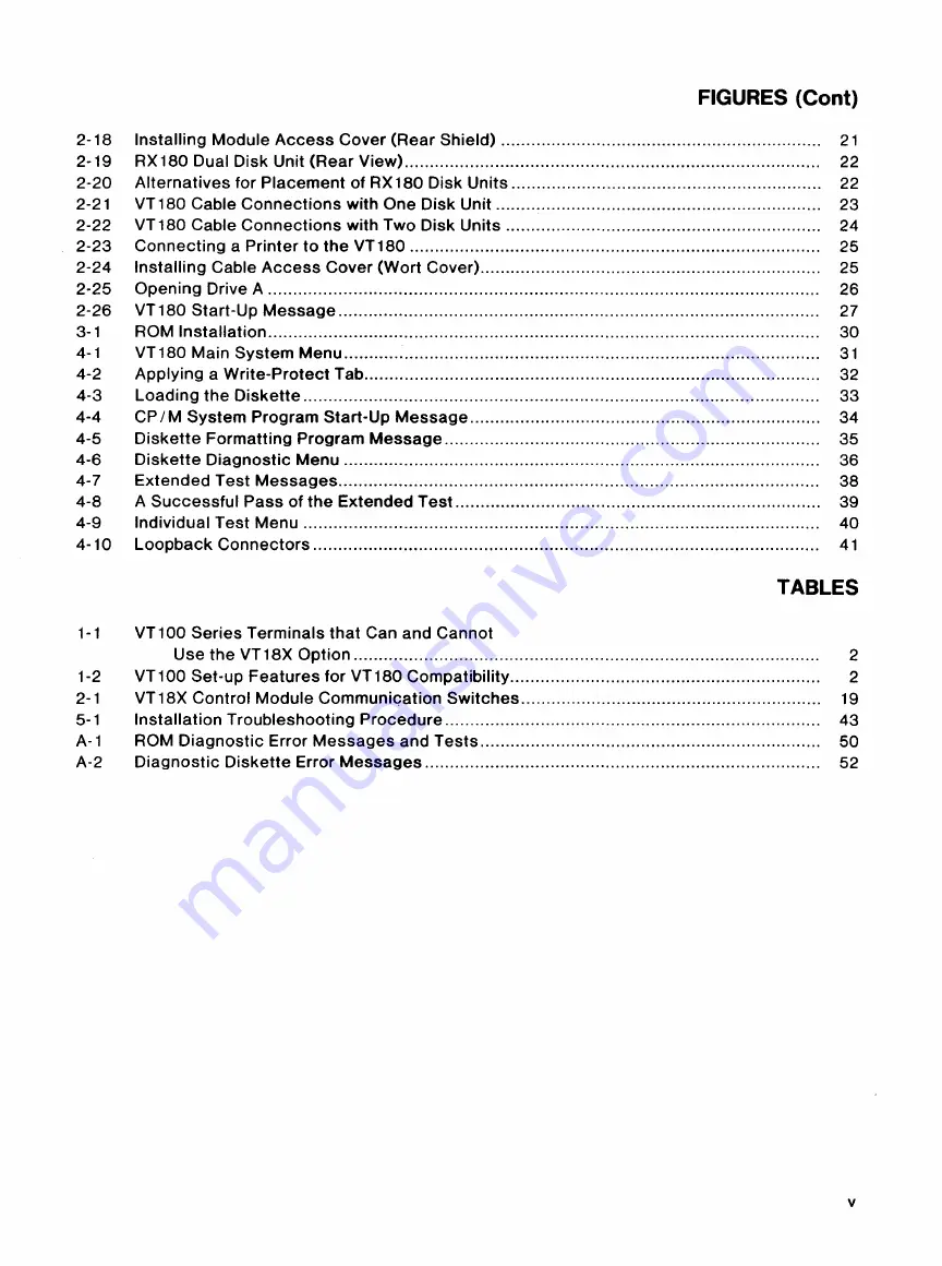
Page 5: ...1 2 1 VT100 Video Terminal Rear View 6 2 2 Removing Top Cover 7 2 3 Removing Bottom Cover 8 2 4 Advanced Video Option Removal and Installation 9 2 5 Checking ROM Numbers on Terminal Controller Module 10 2 6 Advanced Video Option with Jumpers 11 2 7 Advanced Video Option with Switches 11 2 8 Installing VT 180 Paddle Board 12 2 9 Disconnecting DC Power Harness 13 2 10 Remove Key Plug from Expansion ...

Page 6: ...in System Menu 31 4 2 Applying a Write Protect Tab 32 4 3 Loading the Diskette 33 4 4 CP M System Program Start Up Message 34 4 5 Diskette Formatting Program Message 35 4 6 Diskette Diagnostic Menu 36 4 7 Extended Test Messages 38 4 8 A Successful Pass of the Extended Test 39 4 9 Individual Test Menu 40 4 10 Loopback Connectors 41 TABLES 1 1 VT100 Series Terminals that Can and Cannot Use the VT18X...

Page 7: ... 3 lists some special procedures to upgrade your VT100 if it already includes the printer port option or a word processing option Chapter 4 provides the system test procedure used to make sure the installation is correct and the diskette formatting procedure Chapter 5 provides some basic troubleshooting procedures to help you isolate and solve problems encountered during installation Some of the d...

Page 8: ...Figure 1 1 VT18X Upgrade Kit This upgrade and system test guide provides the installation procedures to upgrade your VT100 to a VT 180 personal office computer This guide also provides a test procedure to make sure that the installation is correct Table 1 1 lists the VT 100 series models that can and cannot use the VT 18X upgrade kit NOTE Before attempting this installation make sure your VT100 is...

Page 9: ...dit capability The VT180 does not support the 20 mA VT1XX AA or the printer port option VT1XX AL AM AU AV See Chapter 3 for special procedures The terminal can use the VT18X option if it is reconfigured to a basic VT100 but it loses the feature s mentioned Table 1 2 VT100 Set Up Features for VT180 Compatibility Set Up Feature ON LINE I LOCAL ANSI VT52 AUTO XON I XOFF Wraparound New Line Power Sele...

Page 10: ...us mounting hardware Part Number 54 15152 AA 54 15150 54 13384 01 74 25604 01 74 26146 74 26145 12 12405 70 08612 0M RX180 AB 17 00297 17 00150 01 The following parts are included with a second disk unit order number RX 180 AE Part 1 1 1 RX 180 AD dual disk unit drives C and D BC26Z cable disk to disk Line cord Part Number RX180 AD 17 00298 17 00150 02 The tools needed for installing the VT18X upg...

Page 11: ...the back of the VT 100 to 0 Figure 2 1 Remove the ac line cord from the wall receptacle and from the back of the VT100 2 Unplug the keyboard and the communication cables if attached to the back of the terminal Unplug any video in or video out cables See Figure 2 1 3 With a screwdriver loosen the four captive screws from the module access cover at the back of the terminal Remove this cover it will ...

Page 12: ...UPGRADE KIT INSTALLATION VT18X CAPTIVE SCREW __ COMMUNICATION POWER CORD I Rear View V dec Termma VT100 I Figure 2 1 6 POWER SWITCH MR 7863 ...

Page 13: ...PGRADE KIT INSTALLATION VT18X U MR 7248 Top Cover 2 Removmg Figure 2 7 ...

Page 14: ...e chassis during shipment Figure 2 3 Save these screws if the terminal is to be sent to another location otherwise discard them Turn the terminal upright b Find the four pop fasteners holding the chassis to the bottom cover Pull the fasteners up until they click c With two hands lift the chassis by its center support bar up and out of the bottom cover REMOVE SCREWS 4 PLACES MA 7971 Figure 2 3 Remo...

Page 15: ...ller module With needlenose pliers press each standoff together while lifting up on the AVO 3 Remove any module installed in the STP connector on the terminal controller module Figure 2 4 The printer port option VT1XX AC is not used in this computer If a printer port option is removed go to Chapter 3 for special instructions if not continue with the next step ADVANCED VIDEO OPTION TERMINAL CONTROL...

Page 16: ...ler module may be installed in either order illus trated in Figure 2 5 ORDER A ORDER B D 54 13009 03 I CHARACTER GENERATOR D J6 22 ROM 3 23061 E2 23034E2 OM 33 E ROM 1 23033E2 23 032E2 t t J ROM 0 23034E2 23061 E2 NOTE ROMS MAY BE INSTALLED IN EITHER ORDER A OR B ON TERMINAL CONTROLLER MODULE MR 7064 Figure 2 5 Checking ROM Numbers on Terminal Controller Module 2 If previously removed check for th...

Page 17: ...8X UPGRADE KIT INSTALLATION JUMPERS c J11 c J 12 c J13 c J 14 MA 7073 Figure 2 6 Advanced Video Option with Jumpers I o w ALL S1 OFF z Jl I O l J Xl MR 7074 Figure 2 7 Advanced Video Option with Switches 11 ...

Page 18: ...lace one end of the 16 conductor ribbon cable in connector J2 on the VT180 paddle board observing the red line on the cable as shown in Figure 2 8 Extend the cable to the right of the module TERMINAL CONTROLLER MODULE I L oU I_ f TO J3 ON VT18X CONTROL MODULE J2 STP CONNECTOR VT180 PADDLE BOARD FIBER SPACER FIBER SPACER NYLON WASHER ION REVERSE SIDE j4 40 X 1 4 IN sC7W Cl mrrmrO J2 VT180 PADDLE BO...

Page 19: ...BACKPLANE The expansion backplane shipped with the VT18X has a key plug in connector J6 on the back plane Figure 2 10 This key plug is for the new VT100 terminal controller module 54 13009 03 which has a slot in its connector J6 between pins 5 and 6 When installing the VT18X inspect your terminal controller board for a notch in connector J6 Fig ure 2 5 If the notch is not present you will have to ...

Page 20: ...ollows 1 Find four 4 40 X 1 2 inch screws two round fiber spacers and four kep nuts in the small parts box 2 Install two screws from the inside of the chassis so they line up with the top and bottom holes of connector J6 on the expansion backplane See Figure 2 12 3 Fasten the backplane to the card cage with kep nuts 4 Install the other two screws at location J4 of the backplane using a spacer betw...

Page 21: ...VT 18X UPGRADE KIT INSTALLATION CHASSIS MR7876 Figure 2 12 Installing Expansion Backplane 15 ...

Page 22: ...Use the following procedure to add the RF shield to the video terminal NOTE Set the chassis on a protective material to protect the terminal s parts as well as the sur face you are working on 1 Set the chassis on end with the card cage up 2 Remove the four 1 4 inch hex head screws from the card cage two on the top and two on the bottom 3 Slide the RF shield on the card cage as shown in Figure 2 14...

Page 23: ...t to another location turn the terminal on its left side and install the screws previously removed from the bottom CHANGE LOGO Use the following procedure 1 With a small screwdriver and pliers remove the two retaining rings that hold the VT100 logo to the inside of the top cover 2 Remove the VT100 logo and replace it with the VT180 logo See Figure 2 15 3 Secure the VT180 logo with the two retainin...

Page 24: ...TROL MODULE Use the following procedure 1 Check the communications switches on the VT 18X control module Figure 2 16 for the cor rect positions listed in Table 2 1 The switches allow you to set the VT180 to run on most full and half duplex communications modems with application software Switches 2 and 6 must be on for the communications port to function The other switches may be enabled for the ty...

Page 25: ...o Send From VT180 4 105 CA 2 On CTS Clear to Send To VT180 5 106 CB 3 Off SCTS Secondary Clear to To VT180 13 Send 4 On SPDI SpeedIndicator FDX To VT180 12 SRLSD Secondary Carrier Detect HDX 5 On SRTS Secondary Request to From VT180 11 Send 6 On TXD Transmitted Data From VT180 2 103 BA 7 Off STXD Secondary Transmitted From VT180 14 Data 8 On SRTS Secondary Request to From VT180 19 Send 9 Off Not u...

Page 26: ...TOR PORT DISK DRIVE PORT VI LJOO _R E0 LI NE COMMUNICATIONS PORT VT18X CONTROL MODULE MR 7089 Figure 2 17 Installing VT18X Control Module INSTALL NEW METAL MODULE ACCESS COVER REAR SHIELD Install the new metal module access cover over the module access opening aligning its holes with the connectors on the module Install this cover as follows 1 Place one 1 1 8 inch hex standoff 90 00001 12 in each ...

Page 27: ...and B RX180 AD includes drives C and D 1 Check the voltage selector on the back of each disk unit it should match your power require ments See Figure 2 19 CAUTION If you connect 220 V to a disk unit that is set for 115 V you will blow its fuse and may damage its power supply 2 If you have one disk unit you can place it on top or on either side of the video terminal See Figure 2 20 NOTE If you plac...

Page 28: ...F SWITCH AC POWER OUT MR 7867 Figure 2 19 RX 180 Dual Disk Unit Rear View PLACEMENT FOR TWO UNITS r I I I I I I I I ______J I n U U I r 1 11 I L_ J I t r r 1 W b U U I f1i I J9 I I 1 I I I MR7879 Figure 2 20 Alternatives for Placement of RX180 Disk Units 22 ...

Page 29: ...the video terminal and attach this ac line cord to the ac input of the top or only disk unit Figures 2 21 and 2 22 Do not plug the other end of this cable into an ac wall receptacle at this time 7 If you have two disk units plug the end of a coiled line cord with prongs into the ac output of the top disk unit and plug the end without prongs into the ac input of the bottom disk unit 8 Plug the end ...

Page 30: ...r cable make sure it has a right angled female con nector to attach to the VT180 and is wired as follows Connector 1 Pin 1 Pin 2 Pin 3 Pin 6 Pin 7 Pin 20 Connector 2 Pin 1 Pin 3 Pin 2 Pin 20 Pin 7 Pin 6 1 Attach the right angled female connector of the null modem cable to the 25 pin printer con nector on the top left side of the module access cover See Figure 2 23 2 Attach the other end of this ca...

Page 31: ...s within the opening at the bottom of the cable access cover and fasten this cover to the standoffs on the rear shield with four 6 32 X 5 16 inch Phillips head screws See Figure 2 24 PRINTER CONNECTOR PORT I ERAL PURPOSE PORT rA jr L7 111 J 1111111111 1111111ft 1111 1111 MR 7887 Figure 2 24 Installing Cable Access Cover Wort Cover 25 ...

Page 32: ...rd that was inserted for protection during shipment PUSH TO OPEN MA 7024 Figure 2 25 Opening Drive A 4 Set the 1 0 switch on the back of the video terminal to 1 5 If two disk units are installed set the 1 0 switch on the bottom disk unit to 1 NOTE If two disk units are installed the 1 0 switch on the bottom disk unit should stay at 1 on Power for the entire system is turned on and off by the 1 0 s...

Page 33: ...llnal Mode MR 7880 Figure 2 26 VT 180 Start Up Message The drive select red light on the front of the top or only disk unit should come on This is disk drive A The 1 0 switch for each disk unit should light up NOTE If these power indications do not occur refer to Table 5 1 to find and correct the problem Continue with the system test procedure in Chapter 4 NOTE To turn the system s power off simpl...

Page 34: ...port option ROM Socket Remove ROMs Install ROMs ROMO 23 095E2 23 061E2 ROM 1 23 096E2 23 032E2 ROM 2 23 139E2 23 033E2 ROM3 23 140E2 23 034E2 You can order new ROMs using the part numbers listed above by contacting your local DIGITAL sales office 3 Unpack the ROM from its container but do not remove it from the conductive foam Press the foam against the surface of the terminal controller module to...

Page 35: ...rocessing terminal VT100 WA or WB can be upgraded to a VT180 A word pro cessing terminal has one ROM installed in the ROM A position on the advanced video option AVO Figure 2 6 or 2 7 The ROM part number and the jumpers installed or the switches set on the AVO are as follows 30 ROMA Part Number 23 069E2 Jumpers Installed 1 and 7 all others removed See Figure 2 6 Switches Set 2 and 8 in switch pack...

Page 36: ...te in disk drive A Before you can run this diagnostic successfully you must learn how to format a diskette This procedure is provided in this chapter ROM BASED DIAGNOSTIC The ROM based diagnostic runs automatically on power up and checks the internal logic of the VT 180 modules This diagnostic assumes no diskette is loaded If the ROM based diagnostic runs successfully the Main System menu prints o...

Page 37: ...ix FORMATTING DISKETTES Before you can run the VT18X diskette diagnostic you need two formatted diskettes Formatting a diskette sets up the track pattern on a new diskette erases the data on the diskette and leaves it blank When formatting you should be careful not to mistakenly erase the wrong diskette Do not format the system diskette or the diagnostic diskette The formatting procedure takes abo...

Page 38: ...MA 7878 Figure 4 3 Loading the Diskette 33 ...

Page 39: ...K IN DRIVE B TYPE RETURN TO CONTINUE E TO EXIT RETURN A message on the left side of the screen informs you which track is being formatted F and verified V The message is as follows F V TRACK 0 39 After formatting the last track the program displays a completion message as follows V TRACK 39 DISK FORMAT VERIFY COMPLETE 6 Place a new diskette in drive B to format a second diskette INSERT NEW DISK IN...

Page 40: ...access drive B as follows A B RETURN Drive B should now become the current drive and the screen should display the following prompt B If the prompt appears the diskette in drive B is properly formatted 9 Verify that the other blank diskette is properly formatted as follows a Remove the system diskette from drive A b Load the other blank diskette in drive A c Type A RETURN d The screen should displ...

Page 41: ... This selection allows you to run all the tests described previously one at a time on the drive you select In addition there are tests to check the communication ports a printer if installed and syn chronous communication Run time for these tests depends on the tests you select The error messages for this diagnostic are listed in the appendix Booting the VT18X Diskette Diagnostic Turn the system o...

Page 42: ...n suc cessfully after about 2 minutes 45 seconds the program automatically switches to drive B If you selected a four drive system the program will halt after testing drive B and instruct you to move the formatted diskettes to drives C and D If you forgot to install a diskette in the drive or if you left its door open the following error message appears on the video screen ERROR No index pulse no ...

Page 43: ...owed by the other messages shown in Figure 4 7 FLOPPY DISK DIAGNOSTIC TESTS rel 1 1 Driue A Selected Endofpart13 Dril e B Selected End of part 13 TEST PASSED 2 Ralll Test REFRESH TEST ADDRESS I NG TEST DATA INTEGRITY TEST TIME TO COMPLETE 132 CODE E ECUTIoN TEST GALLOP TEST ALPHA TEST T I ME TO COMPLETE OOGO TEST PASSED 3 Basic ColllfTl Test No Loop Bacf Plug RTC TEST PR I NTER GENERAL PURPOSE POR...

Page 44: ...UP 0 to exit to the Main System menu Individual Tests To test a printer or to test a specific communications port use the individual tests Select these tests by typing 3 The Individual Test menu prints on the video screen as shown in Figure 4 9 Type the number of the test you want to run and follow the instructions printed on the video screen for that test The terminal echoes the number of the tes...

Page 45: ...line driv ers and receivers which are not checked on power up or during self test The transmit and receive baud rates for the terminal must also be identical 2 The printer confidence tests 7 and 8 send a line of text that you type to the printer The printer must be set up for these parameters Baud rate 1200 Bits character 8 Parity None Stop bits 1 3 The synchronous communications test 9 requires t...

Page 46: ...computer 1 Reset the VT180 by pressing SET UP O 2 The VT180 prints the Main System menu 3 Ask the customer to check the terminal mode by pressing T and to communicate with the host computer This ensures that the communications features of the VT180 are set up correctly for the host computer 4 If you cannot communicate with the host computer you may have to change the commu nications switches on th...

Page 47: ... cause Table 5 1 Installation Troubleshooting Procedure Symptom or Error Message No response when power switch is set to the on position The on off 1 0 switches on the disk units are not on The lights on the keyboard are not on Disk unit on off 1 0 switch light is off Terminal is on Probable Cause Not plugged in no power at wall socket Main power fuse Disk unit fuse AC line cord Power cable is inc...

Page 48: ... not attached to expansion backplane Terminal power supply Expansion backplane The two disk units are installed in reverse order Terminal powers up in local mode Terminal is set up for VT52 format The diskette installed in the disk drive is blank Corrective Action Check for correct daisy chain of power through each disk unit to the terminal Check setting of on off 1 0 switches on each disk unit an...

Page 49: ... no diskette is loaded in drive A You tried to boot the system disk in a drive other than drive A but you did not have a formatted diskette loaded in drive A The diskette you tried to format has a write protect tab on it or it is loaded upside down in drive Corrective Action Place system diskette fully in drive and make sure the door is closed Reset terminal and reboot diskette With two disk units...

Page 50: ...e configured for drives A and B Door on selected drive is open no diskette is in drive or drive is not connected The diskette in the drive is unformatted or write protected Unformatted diskette in drive EMI static from video terminal or disk drive failure Corrective Action Format the diskette and try again Place a formatted diskette in drive A before selecting self test Place a formatted diskette ...

Page 51: ...laX control module You have just changed ROMs on the terminal controller module and the NVM needs to be reset Keyboard is disconnected Keyboard Terminal controller module advanced video module or keyboard Screen brightness is too low ROMs on controller may need to be changed Corrective Action Try booting another diskette Repeat test procedure in Chapter 4 using another diagnostic diskette Check LE...

Page 52: ... incorrectly Parity feature is set incorrectly to match computer Communications switches on VT 18X control module may be set incorrectly Controller ROMs Parity feature is set incorrectly XON XOFF not supported by host or turned on Transmit or receive speed is set incorrectly Corrective Action Enter SET UP Band check features See Table 1 1 for VT100 VT 180 compatible features Set transmit or receiv...

Page 53: ...APPENDIX VT18X ERROR MESSAGES A 1 ROM DIAGNOSTIC ERROR MESSAGES Table A 1 lists the ROM diagnostic error messages that may occur on power on reset or self test 49 ...

Page 54: ...TC FAILURE Real time clock y y y VT 18X control module 1 2 4 yes test TERMINAL PRINTER General purpose y y y VT 18X control module 2 4 no FAILURE printer ports CONSOLE FAILURE Console port test c no c VT18X control module 1 4 yes COMM PORT FAILURE Communications c no c VT 18X control module 4 yes for port test terminal mode no for diskette boot mode FLOPPY ERROR Floppy y y y VT 18X control module ...

Page 55: ...f test disk drive cable or VT 18X control module FLOPPYERROR READ Floppy controller no no y Faulty diskette disk 2 no SECTOR FAILURE drive test 6 drive cable or VT 18X DRIVE x control module DISKETTE BOOT System loader on no no no No diskette in drive 1 no FAILURE or ROM diskette could not disk 1 drive door is DISK LOADER transfer to system open no system FAILURE memory diskette loaded wrong drive...

Page 56: ... ERROR Step in error controller module bad ERROR Direction output low controller module bad ERROR Direction output high controller module bad ERROR Step in error ERROR Timing wrong for single track move too fast ERROR Timing wrong for single track move too slow ERROR Seek not completed in time with no verify controller module bad ERROR Seek not completed in time with verify disk ERROR Track 0 bit ...

Page 57: ...ERROR Record not found error disk ERROR Write fault controller module bad ERROR Write protected ERROR Bad data ERROR Ready Set controller module bad ERROR Busy Set ERROR Lost data controller module bad ERROR Timing wrong for motor shut off controller module bad ERROR Motor select bit high controller module bad ERROR One shot too fast controller module bad Possible Source VT 18X control module VT18...

Page 58: ...AM FAILURE BIT 0 RAM FAILURE BIT 1 RAM FAILURE BIT 2 RAM FAILURE BIT 3 RAM FAILURE BIT 4 RAM FAILURE BIT 5 RAM FAILURE BIT 6 RAM FAILURE BIT 7 ADDRESS FAILURE Communications Test Error Messages INCORRECT VECTOR UNSOLICITED INTERRUPT RTC FAILURE CONSOLE FAILURE COMM FAILURE PRINTER FAILURE GENERALPURPOSEF LURE PRINTER GENERAL PURPOSE FAILURE 54 Possible Source VT l8X control module VT l8X control m...

Page 59: ...ou found in the manual _ Does this manual satisfy the need you think it was intended to satisfy _ Does it satisfy your needs _ Why _ o Please send me the current copy of the Technical Documentation Catalog which contains information on the remainder of DIGITAL s technical documentation Name _ _ Title Company _ _ Department _ Street _ City _ State Country Zip Additional copies of this document are ...

Page 60: ...NESS REPLY MAIL No Postage Necessary if Mailed in the United States FIRST CLASS PERMIT NO 33 MA YNARD MA POSTAGE WILL BE PAID BY ADDRESSEE Digital Equipment Corporation Educational Services Quality Assurance 12 Crosby Drive BUO E08 Bedford MA 01730 ...

Page 61: ...mn nnmn ...

Reviews: