97
<
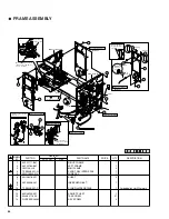
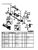
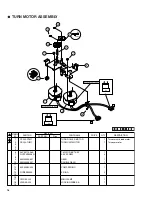
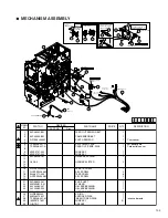
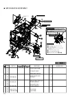
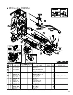
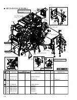
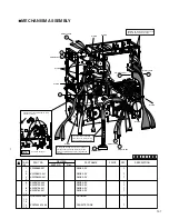
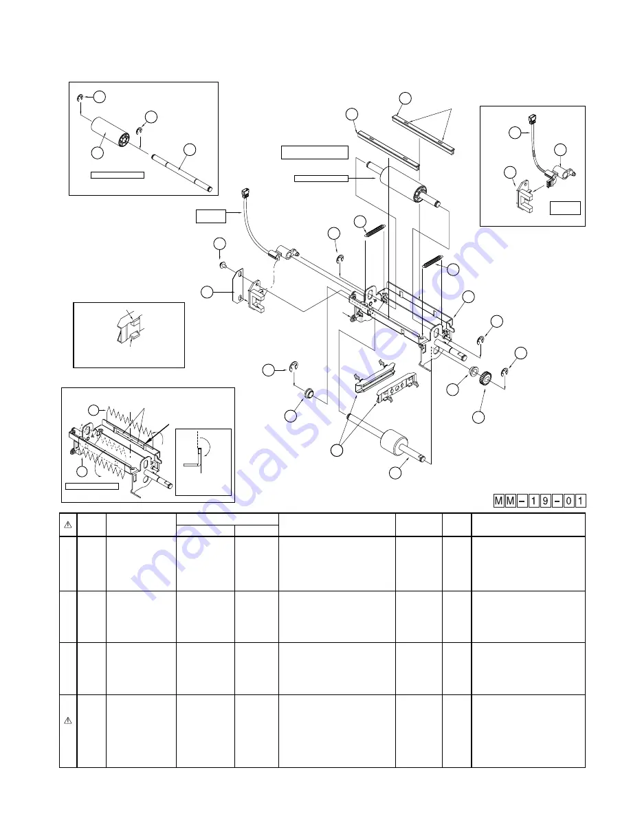
TURN UNIT ASSEMBLY
1
KJU46323-A01
PRESS ROLLER
1
2
KJD45509-A01
PRESS ROLL SHAFT
1
3
4
KJP33133-E0A
TR UNIT BKT ASY
1
5
KJS33103-001
TENSION SPRING
2
6
KJM33118-B01
CARD GUIDE
2
7
KJV45580-B0A
T FEED ROLLER
1
8
KJY44486-002
OIL BEARING
2
9
KJM45516-001
D GEAR
1
10
11
12
KJM45598-001
EDGE COVER
2
13
KJZ45597-A02
BRUSH
2
14
15
QYREE4000X
E RING
2
16
QYREE5000X
E RING
4
17
18
TPS0248-001-B
TURN.CARD SENS.PWB
1
Turnunit card sensor
19
KJU46204-001
PWB SHEET
1
20
KJM45508-001
WIRE GUARD
1
21
QYSBST3006N
TAP SCREW
2
22
KWR16003-001
WIRE ASY
1
SYMBOL
NO.
PRICE
PART NO.
PART NAME
QTY
DESCRIPTION
REVISED
PART NO.
Rev.
PRESS ROLLER SA
15
16
8
15
9
8
1
Explanation drawing 1
5
5
11
19
7
12
12
21
QYSBST
3006Nx2
4
6
x2
Hook side
Spring side
Attach each rail so that a hook side is turned
up and a spring side is turned down.
Explanation
drawing 2
Sensor SA
Explanation
drawing 2
Sensor SA
(-002)
(-002)
16
Install this so that it may be
passed under the springs.
18
22
KWR16003-001
20
Fit the claw onto
bracket.
PRESS ROLLER SA
1
2
Explanation drawing 1
16
16
Sticking Brush
13
13
The brush edge shall be higher than
the edge of the hole.
The brush center shall be positioned on the
center between the two hole.
Stick the brush as shown
from inside of the blacket
to the outside
Explanation drawing 2

