104
<
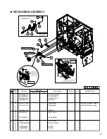
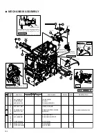
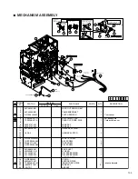
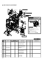
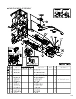
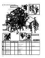
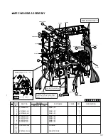
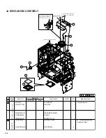
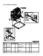
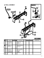
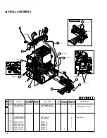
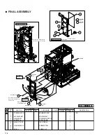
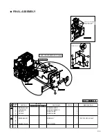
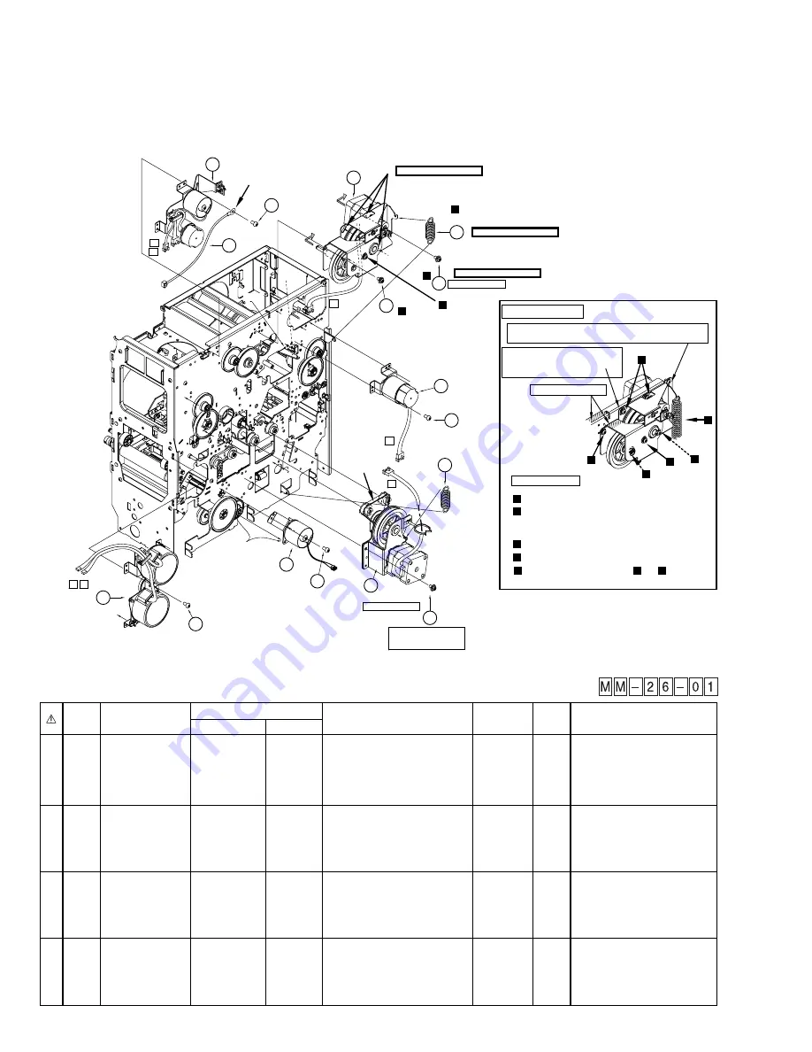
MECHANISM ASSEMBLY
1
PICK UP MOTOR ASY
1
2
3
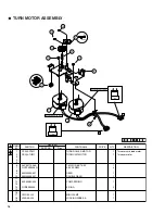
TURN MOTOR ASY
1
4
5
MEDIA W MOTOR ASY
1
6
7
INK S&W MOTOR ASY
1
8
KWS0668-002
WIRE ASY
1
9
10
11
MEDIA SUPPLY MOTOR ASY
1
12
KJS33103-007
TENSION SPRING
1
13
14
FEED MOTOR ASY
1
15
KJS33103-006
TENSION SPRING
1
16
17
18
KJJ46271-003
TAP SCREW
9
19
QYSPSPD4008N
ASY SCREW
7
20
SYMBOL
NO.
PRICE
PART NO.
PART NAME
QTY
DESCRIPTION
REVISED
PART NO.
Rev.
Refer to Explanation drawing 1.
Refer to Explanation drawing 1.
Refer to Explanation drawing 1.
18
1
14
15
19
5
(-006)
18
D3
P5
11
12
19
(-007)
7
18
D1
D2
P3
18
3
Insert the shaft
of gear.
Tighten provisionally
Engage and tension the
belt then tighten the screw
securely.
Set the belt
to the pulley.
19
Tighten provisionally
P1 P2
KWS0668-002
Clamp
Clamp
Fix the wire by screw
as drawing.
8
Secure the two screws.
1
1
1
4
Hook the both ends of the spring.
(Check that he shaded parts of the two brackets
are in parallel.)
3
Loosely secure the three screws
5
1
3
2
Media supply motor installing
procedurer and caution
Explanation drawing 1.
2
1
2
3
4
3
Check that the motor bracket is
not projected higher than the
rear bracket.
Shall be in parallel
After hooking the spring, check that the bracket is not
touch with this screw.
Install procedures
Check that the screw is loosely secured.
Firmly secure the four screws and .
2
3
4

