107
<
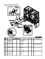
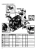
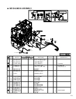
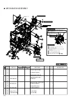
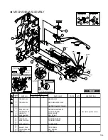
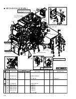
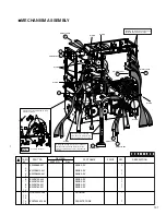
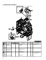
MECHANISM ASSEMBLY
1
KWS0685-001
WIRE ASY
1
2
3
KWR18412-001
WIRE ASY
1
4
KWR18430-001
WIRE ASY
1
5
6
KWS0742-002
WIRE ASY
1
7
KWS0743-002
WIRE ASY
1
8
KWS0756-001
WIRE ASY
1
9
KWS0769-001
WIRE ASY
1
10
11
QGH2502A2-06
HOUSING
1
12
13
14
ZCAT3035-1330
FERRITE CORE
1
15
SYMBOL
NO.
PRICE
PART NO.
PART NAME
QTY
DESCRIPTION
REVISED
PART NO.
Rev.
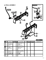
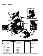
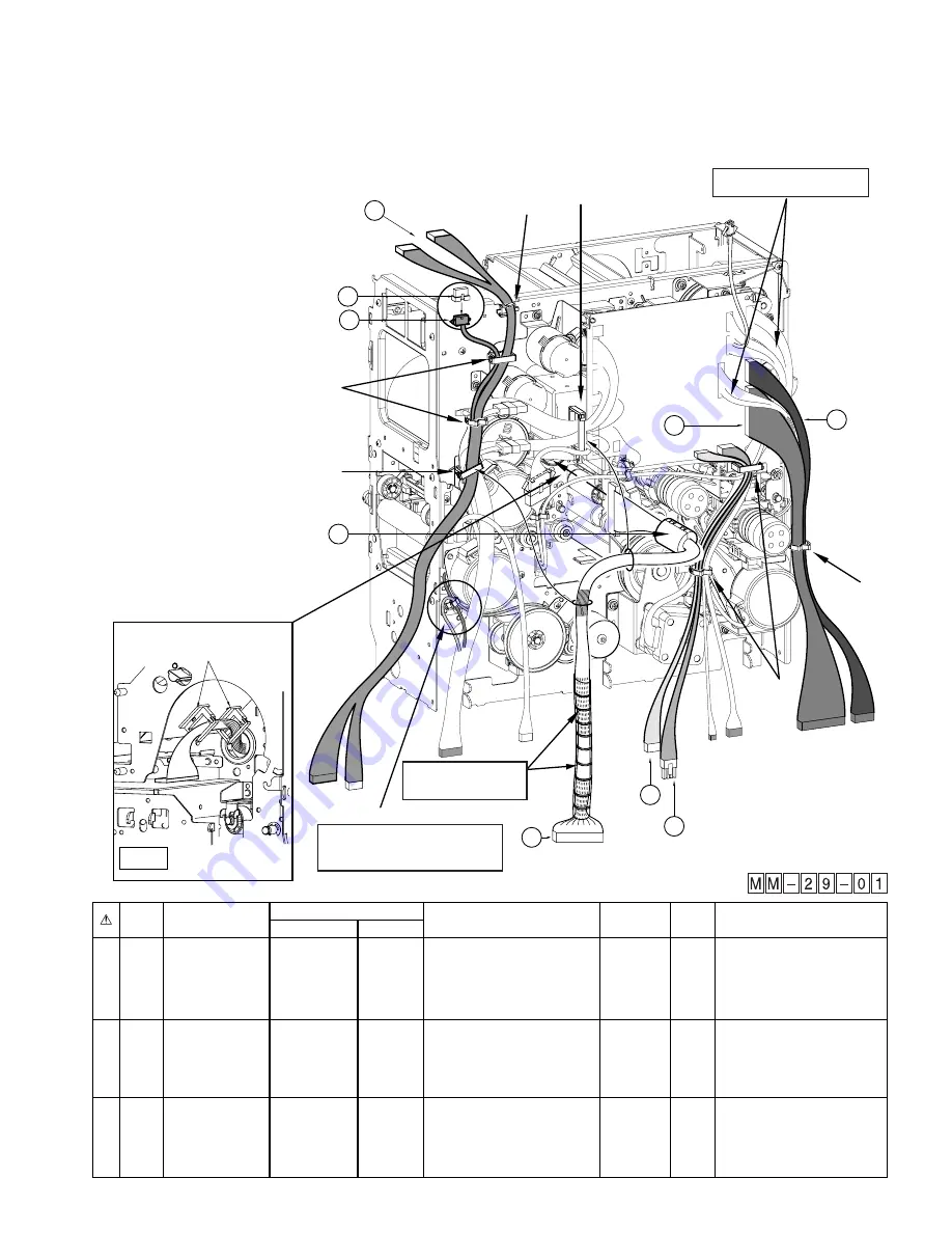
Pass the wire of head through the snap
bush then clamp it.
Head wire treatment
Explanation
drawing 1
8
KWS0756-001
7
6
1
KWS0685-001
KWS0743-002
KWS0742-002
3
KWR18412-001
KWR18430-001
4
J2
J1
J3
J4
J8
KWS0769-001
11
9
CLAMP
CLAMP
CLAMP
CLAMP
TURN OVER
FEED MOTOR
CLAMP
14
CLAMP
CLAMP
Only the J8 cable shall be inserted
between the J3 and J4 cable.
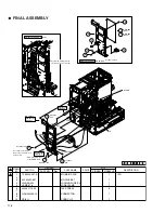
The spiral tube shall fully
cover the area where wires
are separated on the cable.
Clamp the orange wire (for the card near
empty sensor) and the red wire (for the
turn over positioning sensor) together as
shown


