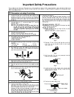
IMPORTANT SAFETY PRECAUTIONS
INSTRUCTIONS
MODEL NAME
................................................................................. 1
1. Detailed specifications .................................................................... 1
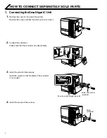
HOW TO CONNECT SEPARATELY SOLD PARTS
.................. 2
1. Connecting the Small IC Unit .......................................................... 2
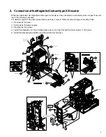
2. Connection of the Magnetic/Contact-type IC Encoder .................... 3
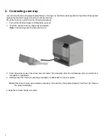
3. Connecting card tray ....................................................................... 4
BLOCK DIAGRAM
.......................................................................... 5
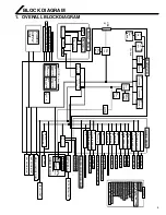
1. OVERALL BLOCK DIAGRAM ......................................................... 5
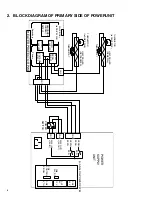
2. BLOCK DIAGRAM OF PRIMARY SIDE OF POWERUNIT ............. 6
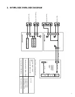
3. INTERLOCK SW BLOCK DIAGRAM .............................................. 7
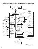
4. BLOCK DIAGRAM OF THE FPGA CIRCUMFERENCE
ON A CPU BOARD ................................................................... 8
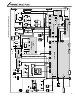
WIRING DIAGRAM
....................................................................... 9
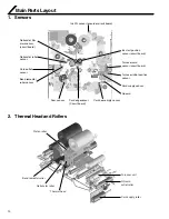
Main Parts Layout
.......................................................................... 10
1. Sensor-related ............................................................................... 10
2. Related to Thermal Head and Rollers ........................................... 10
3. Motor-related ................................................................................. 11
4. Solenoid-RELATED ....................................................................... 11
5. Switch-related ............................................................................... 12
6. Related to Circuit Boards, Power Supply Unit, and Fans .............. 12
7. RF-ID ............................................................................................. 14
REMOVAL AND EXCHANGE OF THE MAIN PARTS
............ 15
1. CHECKING AT THE TIME OF SERVICING .................................. 15
1.1 REMOVE THE TOP COVER AND THE REAR PANEL. .......... 15
1.2 REMOVE THE MG CIRCUIT BOARD. .................................... 15
1.3 SWING DOWN THE POWER SUPPLY UNIT. ........................ 16
2. REMOVAL AND EXCHANGE OF THE MAIN PARTS ................... 16
2.1 REMOVAL OF THE HEAT ROLLER ....................................... 16
2.1.1 Removal of the Bend Remedy Roller ............................... 16
2.1.2 Removal of the Heat Roller .............................................. 16
2.2 REMOVAL OF THE CAM MOTOR .......................................... 17
2.2.1 Installation of the Cam Motor ........................................... 18
2.3 REMOVAL OF THE RETRANSFER FILM SUPPLY
MOTOR ............................................................................ 18
2.3.1 Installation of the Retransfer Film Supply Motor ............... 19
2.4 REMOVAL OF THE RETRANSFER FILM TAKE UP
FILM WINDING MOTOR .................................................. 20
2.5 REMOVAL OF THE CARD FEED MOTOR ............................. 20
2.5.1 Installation of the Card Feed Motor .................................. 20
2.6 REMOVAL OF THE INK SUPPLY MOTOR AND
THE INK TAKE-UP MOTOR ............................................. 21
2.7 REMOVAL OF THE TURNOVER MOTOR AND
THE TURNOVER CARD FEED MOTOR .......................... 21
2.8 REMOVAL OF THE CARD PICKUP MOTOR ......................... 21
2.9 REMOVAL OF THE FRONT PANEL ....................................... 21
2.10 REMOVAL OF THE PLATEN SOLENOID ............................ 22
2.10.1 Installation of the Platen Solenoid .................................. 22
2.11 REMOVAL OF THE POWER SUPPLY UNIT ........................ 22
2.12 REMOVAL OF SENSORS AND SWITCHES ....................... 23
2.12.1 Removal of the Cam Sensor .......................................... 23
2.12.2 Removal of the Card Outlet Sensor ............................... 23
2.12.3 Removal of the Ink Encoder Circuit Board ..................... 23
2.12.4 Removal of the External Unit Power Circuit Board ........ 23
2.12.5 Removal of the Turnover Initial Position sensor ............. 24
2.12.6 Removal of the Card Near-empty Sensor ...................... 24
2.12.7 Removal of the No Card Sensor .................................... 24
2.12.8 Removal of the Retransfer roller/
Remedial Roller Sensor ....................................... 24
2.12.9 Removal of the Retransfer Film Mark/Ink Start Position
Sensor Circuit Board and the Card Edge Sensor ... 25
2.12.10 Removal of the C.L. Interlock Circuit Board and
the Card Supply Sensor ....................................... 25
2.12.11 Removal of the Door Interlock Circuit Board .............. 26
2.12.12 Removal of the Cassette Interlock Circuit Board ....... 26
2.12.13 Removal of the Card Tray Interlock Circuit Board ...... 27
2.12.14 Removal of the Turnover Card Sensor
Circuit Board ........................................................ 27
2.13 REMOVAL OF THE TURNOVER UNIT ................................ 27
2.14 FAN REMOVAL .................................................................... 28
2.14.1 Removal of the Thermal Head Cooling Fan ................... 28
2.14.2 Removal of the Suction Fan ........................................... 28
2.14.3 Removal of the Card Cooling Fan .................................. 28
2.14.4 Removal of the Ventilation Fan ....................................... 29
2.15 ROLLER REMOVAL ............................................................. 30
2.15.1 Feed Roller Removal ..................................................... 30
2.15.2 Platen Roller Assy Removal .......................................... 31
2.16 CIRCUIT BOARD REMOVAL ............................................... 32
2.16.1 Removal of the Main Circuit Board ................................ 32
2.17 Thermal Head Exchange Method ......................................... 33
USE OF SERVICE MODE
........................................................... 35
1. Entry into Service Mode ................................................................ 35
2. Explanation of the Various Modes ................................................. 37
2.1 Download ................................................................................ 37
2.2 Maintenance ........................................................................... 37
2.2.1 Offset Prt Y Setting ........................................................... 37
2.2.2 Offset Prt X Setting ........................................................... 37
2.2.3 Offset Trf X Setting ........................................................... 38
2.2.4 Card Stop Position Setting (Offset Card X) ...................... 38
2.2.5 Default LUT Setting .......................................................... 38
2.2.6 Device Type Setting .......................................................... 38
2.2.7 Card Fan Setting .............................................................. 38
2.2.8 TUR Response Setting ..................................................... 38
2.2.9 Compatible Mode Setting ................................................. 38
2.2.10 Setting of the ink sensor level ........................................ 38
2.3 Off-line Test ............................................................................. 39
2.3.1 Pattern setting .................................................................. 39
2.3.2 Printing Side ..................................................................... 40
CONTENTS


