16
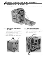
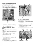
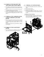
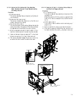
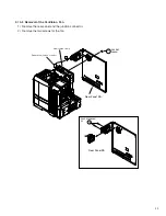
1.3 SWING DOWN THE POWER SUPPLY UNIT.
1) Remove the two screws B on both sides.
2) Loosen the four screws A on both sides.
3) Raise the power supply unit and swing it down.
4) Remove the thermostat cable from the clamper, raise
the power supply unit once, and then swing it down.
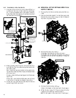
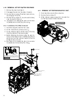
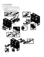
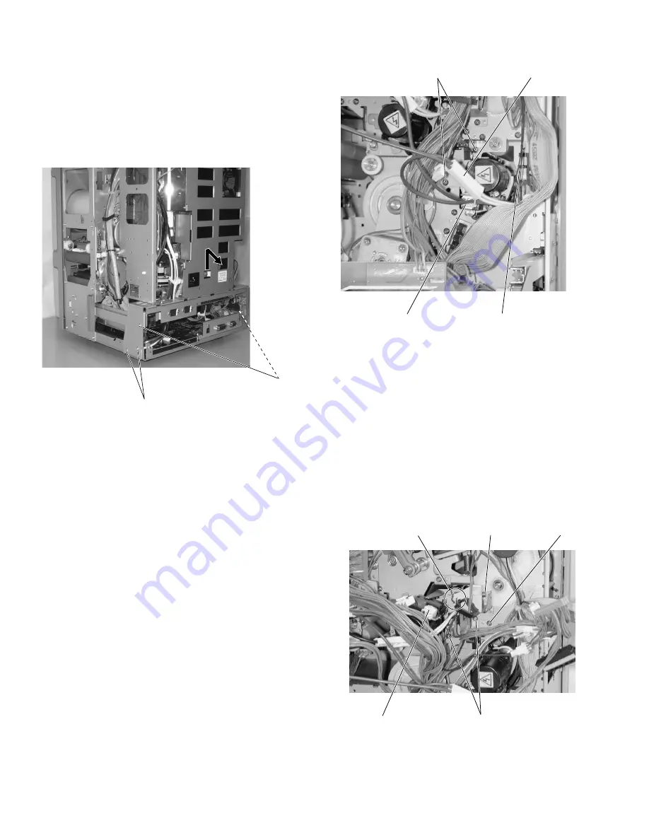
2.1.2 Removal of the Retransfer Roller
1) Disconnect the right side of the spring.
2) Remove the screw A and bring the sensor bracket
to free condition.
For installation, match the notches so that they en-
gage.
3) Disconnect the junction connectors of the thermis-
tor and the thermostat of the retransfer roller.
Remove the power connector.
4) Remove the two screws B and remove the roller by
pulling it slowly to the front.
2. REMOVAL AND EXCHANGE
OF THE MAIN PARTS
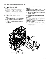
2.1 REMOVAL OF THE HEAT ROLLER
CAUTION:
Immediately after the power has been switched OFF,
the retransfer roller and the bend remedial roller are
still hot.
Please perform the work after these rollers have
cooled down sufficiently, as otherwise burns may
be caused.
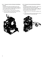
1) Refer to section 2.2 and remove the cam motor.
2) Remove each roller individually.
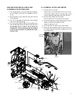
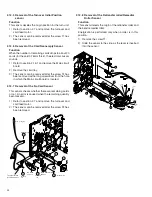
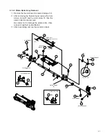
2.1.1 Removal of the Bend Remedial Roller
1) Disconnect the junction connectors of the thermis-
tor and the thermostat of the bend remedial roller.
Remove the power connector.
2) Remove the two screws A.
3) The bend remedial roller can be removed when the
roller is turned upwards and slowly pulled to the front.
Screw B
Power supply unit
Screw A
Screw A
Thermostat wire
Thermistor wire
Power connector
Notch
Spring
Screw A
Screw B
Power connector

