18
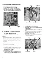
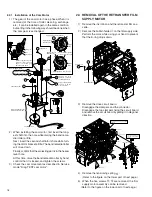
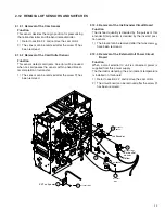
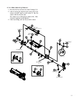
2.2.1 Installation of the Cam Motor
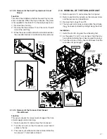
1) The gear of the cam motor has a phase. When it is
removed at the time of roller cleaning, exchange,
etc., it can be installed again in the same condition,
but setting in the following way should be done when
the cam gear is exchanged.
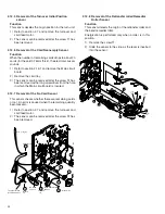
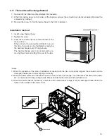
2.3 REMOVAL OF THE RETRANSFER FILM
SUPPLY MOTOR
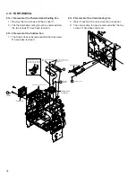
1) Remove the ink ribbon and the retransfer film cas-
sette.
2) Remove the bobbin holder
7
on the film supply side.
Perform the work while using your hand to prevent
that the E-ring drops down.
2) When installing the cam motor, first insert the long-
est shaft into the hole while raising the bend reme-
dial roller a little.
Next, insert the second shaft into its hole while turn-
ing the motor bracket a little. The bend remedial roller
will move down.
Finally, confirm that the projecting part is in the heater
lever hole.
At this time, raise the bend remedial roller by hand,
confirm that it is locked, and tighten the screws.
3) Check the cam movement as described in Service
mode "Diag. TEST cam motor".
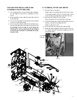
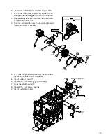
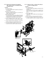
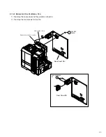
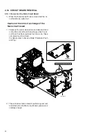
3) Remove the drive circuit board.
Disengage the clampers and the connector.
Disengage the two clampers fixing the circuit board
and remove the circuit board by pulling it in diagonal
direction.
9
10
14
13
Stepping motor SA
17
18
Gear setting method
Slit
6
7
QYSPSPD3006Nx2
Double gear
12
Before installing the gear,
install it on the bracket.
Engage with
the cam gear.
20
Cam gear
P4 Cam motor
QYREE4000X
20
Install so that the slit of the
cam gear comes to the gear
edge of the double gear
when seen from above.
Please use care, as the
installation orientation
can be mistaken easily.
Apply a sufficient quantity
of grease to the two
holes for the shaft.
Apply grease to a small
gear by one grain of rice.
20
Upper
side
Lower
side
Apply grease to this side also
Apply grease to
this side also
Apply sufficient grease
to the hole for the shaft.
Apply grease to this side also
Apply grease to
this side also
8
QYREE4000X
7
Bobbin holder
DRIVE PWB is attached after checking
that the wire passes along 3set in EDGE
SADDLE
J7
(KWS0757-002)
(KWS0751-002)
(Door interlockSA)
F1
D4
P4
P5
P1
P2
P3
D3
J6
J5
J11
DRIVE PWB SA
(Tray interlock)
(Front sensor)
P4
P1
F1
F3
D4
D3
J7
J6
J11
P2
P5
P3
D1 D2
F2
J5
F2
Clamp
Clampx3
D1
D2
The relay connector confirms
and connects with number as
which the connector number
is same.
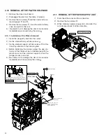
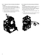
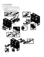
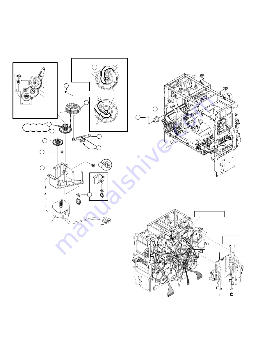
4) Remove the tensioning spring
@
.
(Refer to the figure on the lower part of next page.)
5) When the five screws
&
,
(
are removed, the film
supply motor assembly can be removed.
(Refer to the figure on the lower part of next page.)

