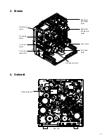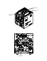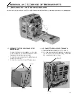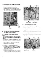
21
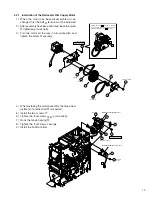
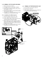
2.6 REMOVAL OF THE INK SUPPLY MO-
TOR AND THE INK TAKE-UP MOTOR
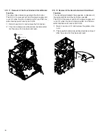
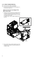
1) When there is an MG circuit board, remove the cir-
cuit board screws and move the circuit board to the
side.
2) Disengage the hook on the left side of the drive cir-
cuit board. Disengage the wire clamp.
3) The ink motor assembly can be removed after the
two screws
*
have been removed. (Refer to a front
page.)
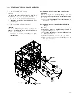
2.7 REMOVAL OF THE TURNOVER MOTOR
AND THE TURNOVER CARD FEED
MOTOR
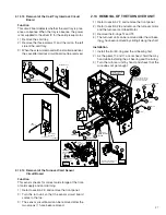
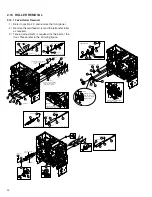
1) The turn over motor and the turn over card feed
motor assembly can be removed after the three
screws
)
have been removed. (Refer to a front
page.)
Remove the spring, as one of the screws is hidden
by the spring.
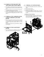
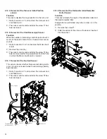
2.8 REMOVAL OF THE CARD PICKUP
MOTOR
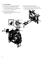
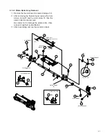
1) The card pickup motor assembly can be removed
after the two screws
*
have been removed.
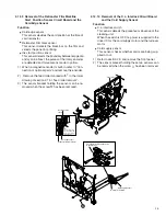
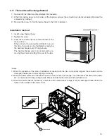
2.9
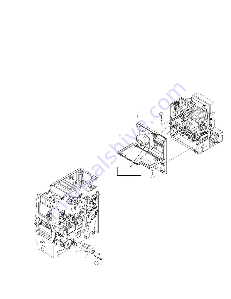
REMOVAL OF THE FRONT PANEL
1) Remove the retransfer film and the ink ribbon cas-
sette.
2) Remove the card tray.
3) Remove the cleaning unit.
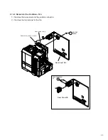
4) When the six screws
4
and the screw
5
for earth
wire have been removed, the front panel can be re-
moved.
Installation of the Front Panel
1) There are two claws at the rear of the front panel.
Insert into the frame by lightly hitting on the claws.
And then secure the six screws
4
.
18
Insert the gear shaft
KJJ46271
-001x2
Card pikup motor
SDSP4008Nx6
4
MG
IC
IS
O
Insert the front panel
into the frame by lightly
hitting on the claws.
5
Front Panel

