22
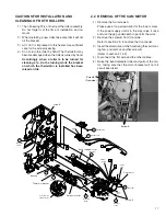
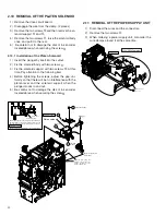
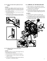
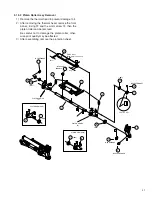
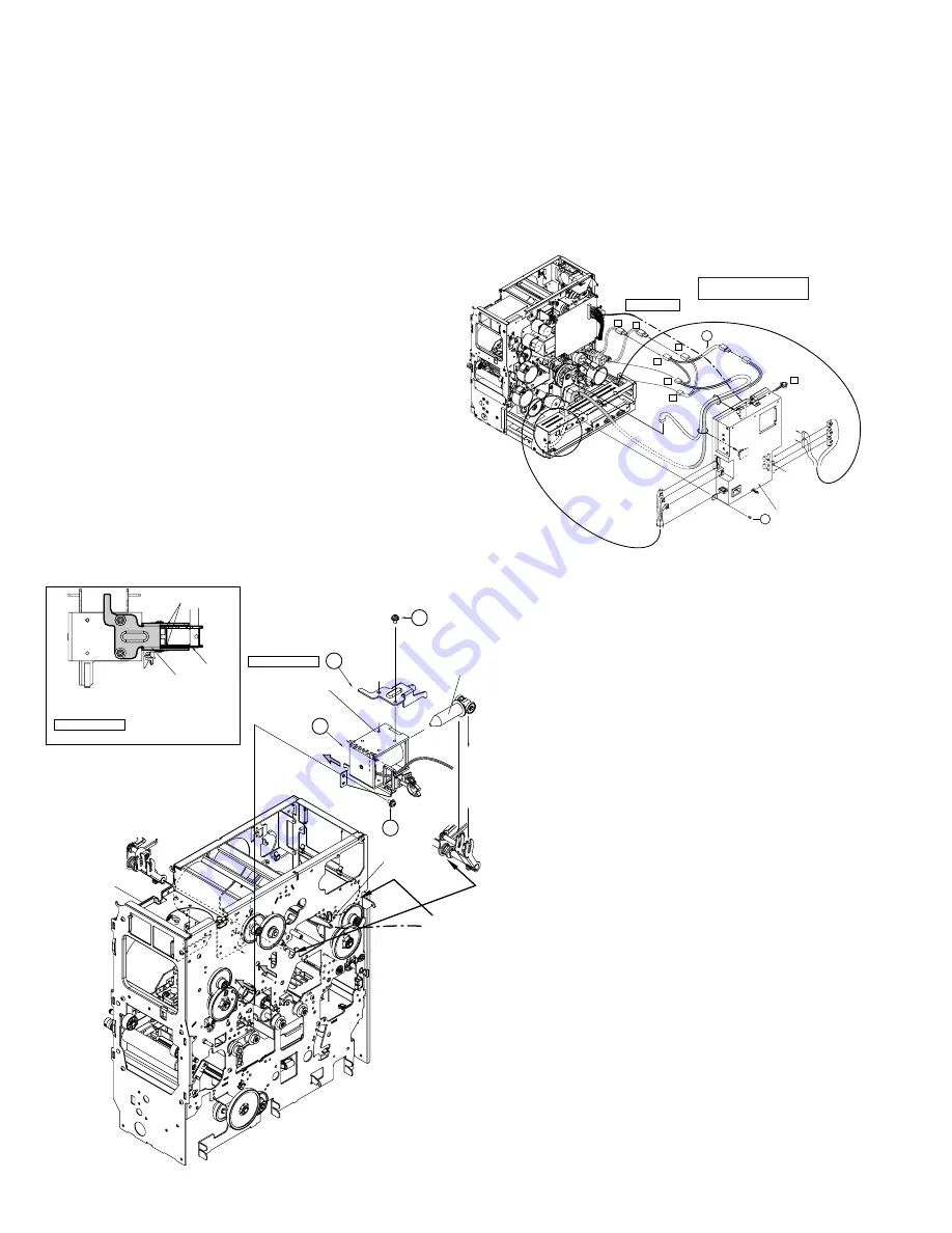
2.10 REMOVAL OF THE PLATEN SOLENOID
1) Remove the drive circuit board.
2) Disengage the wire from the clamp. (2 places)
3) Remove the two screws
(
and then remove the so-
lenoid support
@
and
#
.
4) Remove the two screws
&
, raise the solenoid body
once, and pull it to the rear.
5) Be careful not to damage the disk of ink encoder
located above when removing the screw
(
.
2.10.1 Installation of the Platen Solenoid
1) Insert the plunger by itself into the cutout.
2) Fix the solenoid body with two screws
&
.
3) Fix the solenoid support with two screws
(
. At this
time, Pay attention to the following item.
4) Before tightening the screws, adjust the gap uni-
formly so that there will be no interference with the
platen lever and the solenoid support when the
plunger moves in and out.
5) Be careful not to damage the disk of ink encoder
located above when securing the screw
(
.
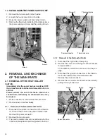
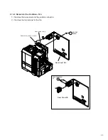
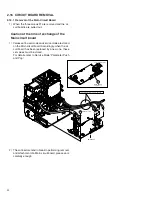
2.11 REMOVAL OF THE POWER SUPPLY UNIT
1) Disconnect the wires and the connectors.
2) Remove the two screws
0
.
3) When ordering a power supply unit, also order the
wire clamps around it at the same time.
Explanation drawing 1
Explanation drawing 1
Engage the bearing with
the rear frame.
11
19
QYSPSPD4008Nx2
(TSS0179)
12
Plunger
17
QYSPSPD
4008Nx2
Clamp
Gap
Platen lever
Solenoid support
Lead the wire along the
bracket so that it does not
become an obstacle on the
inside of the bracket.
Before tightening the screws, adjust the gap uniformly so
that there will be no interference with the platen lever and
the solenoid support when the plunger moves in and out.
Caution for the time of installation of the solenoid support
Platen solenoid
100V/200VCommon
H1
H2
CN8
CN4
CN5
CN6
CN7
CN8
CN4
CN2
CN1
CN3
H1
H2
6
KWS0639-001
POWER SUPPLY SA
F3
H1
H2
10
KJJ46271-003x2
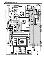
H1=Retransfer heater
H2=Bend Remedial heater

