2.3.3 Times ................................................................................ 40
2.3.4 Test Select ........................................................................ 40
2.4 Diag. Test ................................................................................ 40
2.4.1 Sensor .............................................................................. 40
2.4.2 Actuator ............................................................................ 40
2.4.3 Memory ............................................................................ 41
2.4.4 SIO ................................................................................... 41
2.4.5 Display .............................................................................. 41
2.4.6 Back Color ........................................................................ 41
2.4.7 Buzzer .............................................................................. 41
2.4.8 Registers .......................................................................... 41
2.5 Information .............................................................................. 41
2.6 Parameter Push and Pop ........................................................ 41
OPERATION OF THE MECHANISM
......................................... 42
1. Single-side Printing ....................................................................... 42
2. Double-side Printing ...................................................................... 42
3. Initial Operation ............................................................................. 42
4. Card Supply and Card Feed .......................................................... 43
5. Printing Operation ......................................................................... 45
6. Retransfer Operation ..................................................................... 47
7. Operation in Case of Peeling with Return in Direction Towards
the Turnover Unit ..................................................................... 49
8. Operation of the Turnover Unit ...................................................... 50
9. Others ........................................................................................... 51
9.1 Position Relation with Ink Ribbon and Retransfer Film ........... 51
9.2 Ink Ribbon and Retransfer Film End Treatment ...................... 51
TROUBLESHOOTING
.................................................................. 52
1. LCD Error Code Correspondence ................................................. 52
2. Printing Defects and Countermeasures ........................................ 57
3. Power Supply Check ..................................................................... 61
MAINTENANCE INSPECTIONS
................................................ 62
1. Cleaning ........................................................................................ 62
2. Lubrication ..................................................................................... 62
3. Maintenance Inspections for Main Parts and
Execution Standard ................................................................. 62
4. Periodic Inspection Items .............................................................. 63
5. Trouble Diagnosis Sheet ............................................................... 64
ADJUSTMENT
............................................................................... 65
1. Layout of the adjustment elements ............................................... 65
2. Adjustment .................................................................................... 65
3. Caution Items for the Time of Exchange of
the CPU Circuit Board ............................................................ 65
MG ENCODING UNIT
.................................................................. 66
1. MG Encoding Specifications ......................................................... 66
1.1 Magnetic Encoder Specifications ............................................ 66
1.2 General Equipment Specifications .......................................... 66
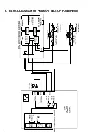
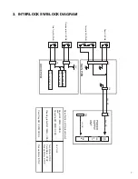
2. Block Diagram ............................................................................... 67
2.1 MG Unit Block Diagram .......................................................... 67
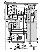
2.2 Connection Diagram ............................................................... 68
3. MG Encoding Unit Exchange Method ........................................... 69
3.1 Repair Classification ............................................................... 69
3.2 Exchange Method ................................................................... 69
3.3 DIP Switch Specifications ....................................................... 71
3.4 MG-related Error Messages ................................................... 72
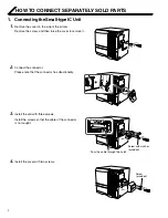
LARGE IC UNIT ....................................................................
73
1. Removal of Each Part ................................................................... 73
1.1 Removal of the Top Cover ....................................................... 73
1.2 Removal of the Front Panel .................................................... 73
1.3 Removal of the Mechanical Unit ............................................. 73
1.4 Removal of the IC Main Circuit Board ..................................... 73
1.5 Others ..................................................................................... 73
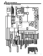
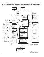
2. Block Diagram ............................................................................... 74
3. DIP Switch Specifications ............................................................. 75
3.1 Specifications .......................................................................... 75
3.2 IC Card Stop Position Adjustment .......................................... 75
4. Error Messages ............................................................................. 76
5. Specifications of Connector on the IC Main Board ....................... 77
EXPLODED VIEW AND ASSEMBLY LISTS
............................ 78
HOPPER ASSEMBLY1/2 — 2/2 ................................................... 79
FRAME ASSEMBLY1/7 — 7/7 ..................................................... 81
PLATEN ASSEMBLY1/1 ............................................................... 88
PICK UP MOTOR ASSEMBLY1/1 ................................................ 89
FEED MOTOR ASSEMBLY1/1 ..................................................... 90
MEDIA W MOTOR ASSEMBLY1/1 ............................................... 91
MEDIA S MOTOR ASSEMBLY1/2 — 2/2 ..................................... 92
INK S&W MOTOR ASSEMBLY1/1 ............................................... 94
HEATER CAM MTR ASSEMBLY1/1 ............................................. 95
TURN MOTOR ASSEMBLY1/1 ..................................................... 96
TURN UNIT ASSEMBLY1/1 ......................................................... 97
MECHANISM ASSEMBLY1/12 — 12/12 ...................................... 98
FRONT PANEL ASSEMBLY1/2 — 2/2 ....................................... 109
PR COMMON ASSEMBLY1/4 — 4/4 ......................................... 111
FINAL ASSEMBLY1/14 — 14/14 ................................................ 115


