25
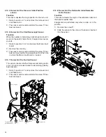
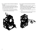
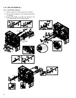
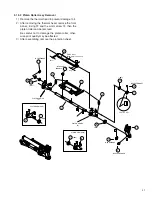
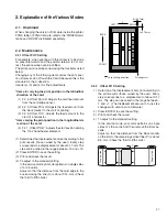
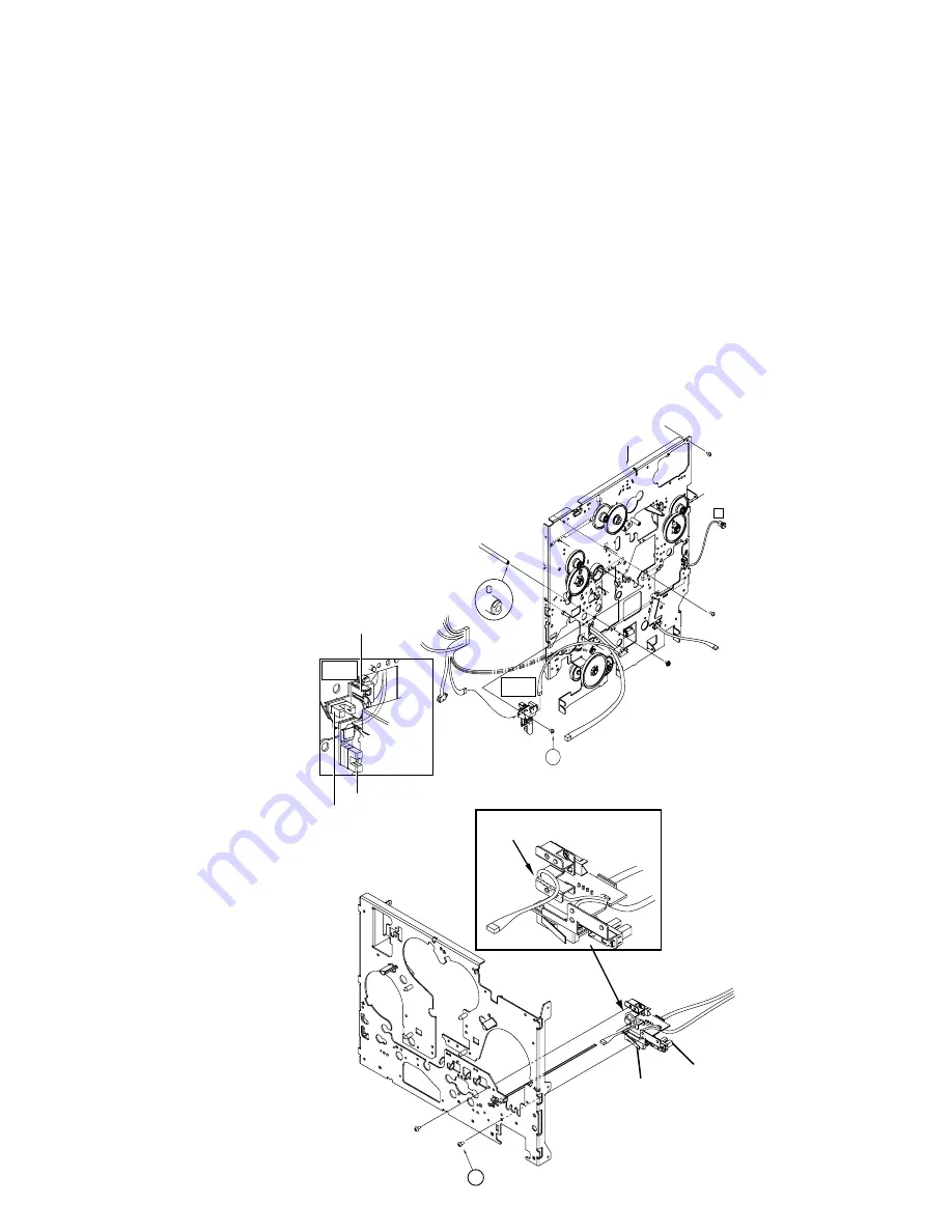
2.12.9 Removal of the Retransfer Film Mark/Ink
Start Position Sensor Circuit Board and the
Card Edge Sensor
Function
•
Card edge sensor
This sensor decides the card position at the time of
card retransfer.
•
Retransfer Film mark sensor
This sensor detects the black bar on the film and
selects the panel for printing.
•
Ink start position sensor
This sensor detects the boundary between magenta
and cyan ink. Next, the pulses of the rotary encoder
are detected and movement is made to yellow.
1) When a magnetic encoder is built-in, refer to "Con-
nection of optional parts" and remove the encoder.
2) Remove the feed roller marked with
*
in the lower
drawing of section 2.15.1 “feed roller removal”.
3) The sensor bracket holding the sensor can be re-
moved when the screw
#
has been removed.
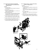
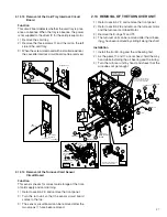
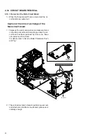
2.12.10 Removal of the C.L. Interlock Circuit Board
and the Card Supply Sensor
Function
•
C.L. interlock switch
This sensor detects the presence or absence of the
cleaning unit.
When the switch is OFF, no power is supplied to the
driver IC for the card supply motor and the turnover
motor.
•
Card supply sensor
This sensor checks whether cards are being sup-
plied or not.
1) Refer to section 2.9 and remove the front panel.
2) The sensor bracket holding these two sensors can
be removed when the screw
6
has been removed.
REAR PLATE SA
13
F1
( side)
Explanation
drawing 4
Explanation
drawing 4
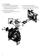
Route the edge sensor
wire underneath the film
mark sensor between
the circuit boards.
Card edge sensor
Retransfer film mark sensor
Ink start position
sensor
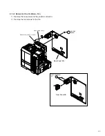
6
Pass the wire through the notch
in the bracket.
Card supply sensor
C. LInterlock switch

