27
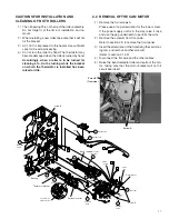
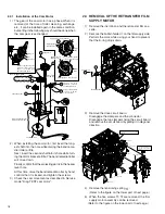
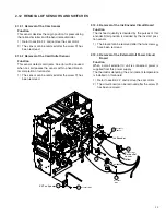
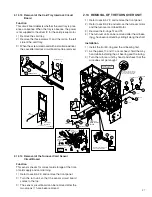
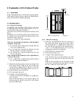
2.12.13 Removal of the Card Tray Interlock Circuit
Board
Function
This circuit board detects whether the card tray is pres-
ence or absence. When the tray is absence, the power
is not supplied to the driver IC for the card pickup motor.
1) Remove the card tray.
2) Remove the three screws
9
and the rail on the left
side of the card tray.
3) When the screw is removed with a small screwdriver,
the cassette interlock circuit board can be removed.
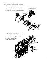
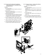
2.13 REMOVAL OF THE TURNOVER UNIT
1) Refer to section 2.9 and remove the front panel.
2) Refer to section 2.8 and remove the turnover motor
and the turnover card feed Motor.
3) Remove the E-rings
$
and
%
.
4) The turnover unit can be removed after the oil bear-
ing
#
has been removed by sliding it along the shaft.
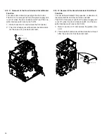
Installation
1) Install the front E-ring and the oil bearing first.
2) As the gears
5
and
6
are not fixed, hold them by
hand while installing the oil bearing and the E-ring.
3) Turn the turnover unit by hand and check that the
wire does not get caught.
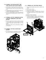
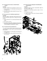
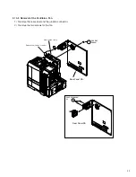
2.12.14 Removal of the Turnover Card Sensor
Circuit Board
Function
This sensor checks for correct card storage at the time
of card supply and card turning.
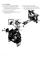
1) Refer to section 2.9 and remove the front panel.
2) Turn the turn unit so that the sensor circuit board
comes to the top.
3) The sensor circuit board can be removed after the
two screws
1
have been removed.
KJJ46271-003
x3
10
QYREE4000X
10
QYREE4000X
5
5
4
9
L. FRAME SA
KWR
10303-010
KJJ46271-003
Card tray
interlock
8
7
14
15
QYREE4000X
QYREE5000X
13
(-002)
Pass the wire
underneath
the sumi tube.
Connect
the connector.
Pay attention to the wire
passing direction.
6
5
x2
Install the gear, holding it so
that it will not drop down.
Attachment position of
the serial number
15
QYREE5000X
13
(-002)
15
10
13
1
(-002)
QYREE5000X
11
16
Q03093-836
Turnover
Card Sensor
Board
Explanation
drawing 2
Explanation
drawing 2
Explanation
drawing 1
Install so that the bracket
of the turn unit goes under
the plate of the rear frame.

